2-4
2.2 Replacement of the main mechanism parts
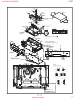
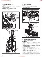
2.2.1 Cassette holder
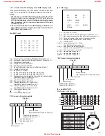
2.2.1.1 Removal
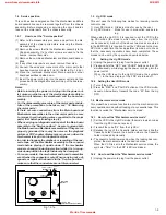
(1) Remove the screws (a) and (b).
(2) Hold up the top frame, cassette holder assembly, drive arm
assembly and side frames (L/R) all together and remove
them by releasing the hooks (a) and (b).
2.2.1.2 Installation (phase adjustment)
(1) Turn gear (a) of the loading motor assembly so that the main
deck connects to the guide hole (a) of the drive lever.
(2) Hook the main deck to hooks (a) and (b).
(3) Place the projection of the drive lever to section (a) of the
side frame (R) and install the cassette holder to the main
deck. Make sure that the bosses of the side frame (L/R) con-
nect with the holes (a) and (b) of the main deck.
(4) Secure screws (a) and (b).
Fig. 2-2-1a
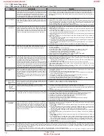
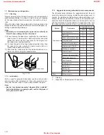
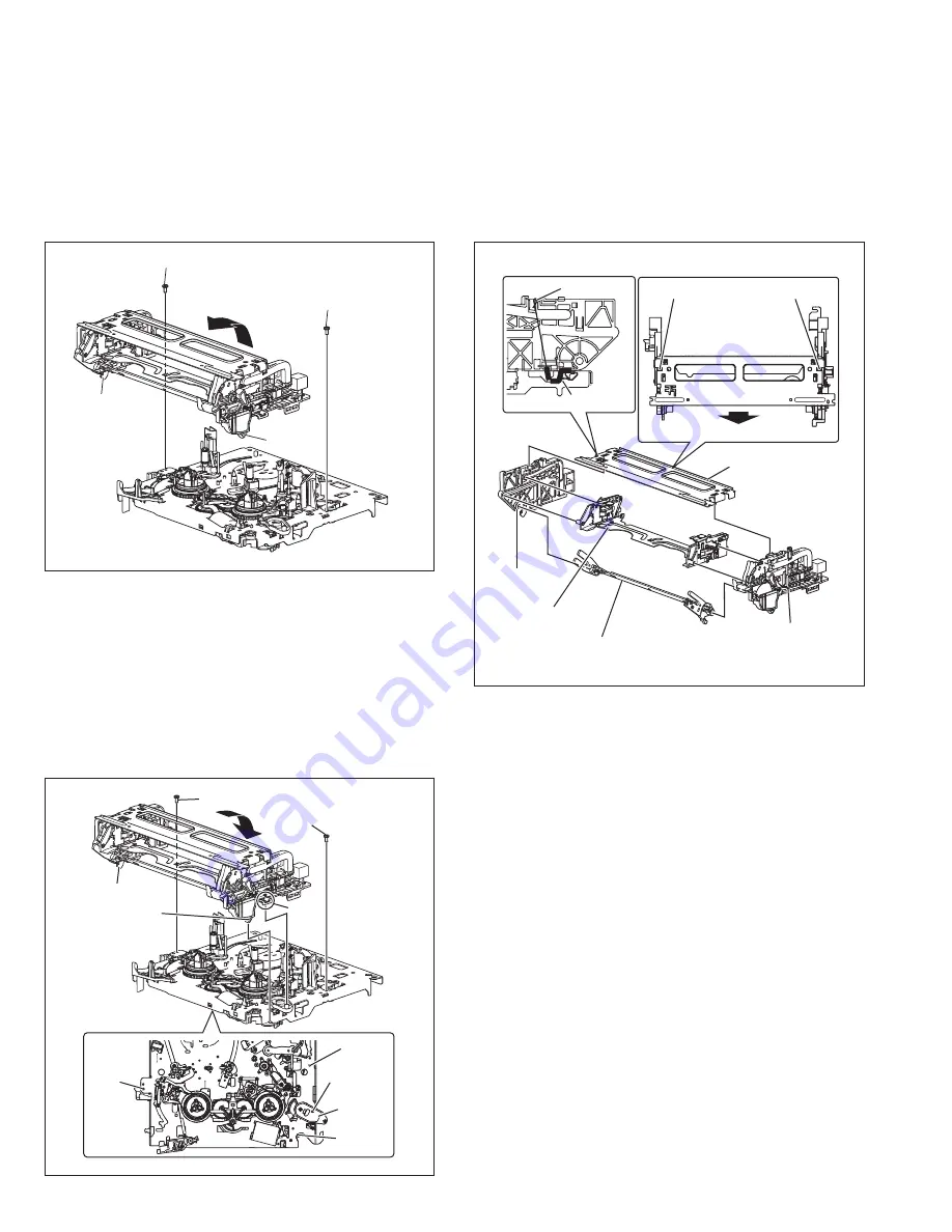
2.2.1.3 Disassembling
(1) Release hook (a) to remove the earth spring (1) from the
top frame.
(2) Release the catches (a) and (b) and pull the top frame in
the direction shown by the arrow (a) to remove it.
(3) Pull out the side frame (R).
(4) Pull out the cassette holder assembly and drive arm assem-
bly from the side frame (L).
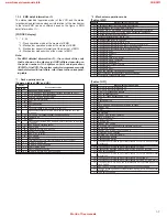
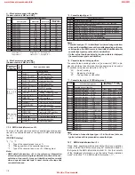
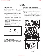
2.2.1.4 Assembling (installation and phase adjustment)
(1) Turn gear (a) of the loading motor assembly so that the main
deck connects to the guide hole (a) of the drive lever.
(2) Place the projection of the drive lever on section (a) of the
side frame (R) and install the side frame (R) to the main deck.
(3) Secure screw (b).
(4) Place section (b) of the drive arm on the gear of the side
frame (R). Make sure that the pin of the door opener con-
nects with section (c) of the drive arm.
(5) Place the drive arm on section (d) of the side frame (L) and
install the side frame (L) on the main deck. Be sure to con-
nect the earth spring (1) to the side frame (L).
(6) Secure screw (a).
(7) Turn gear (a) of the loading motor assembly until the drive
arm is vertical.
(8) Place the slit of the side frame (L/R) at the foot of the cas-
sette holder assembly and install the cassette holder.
(9) Place the top frame on the position guide (a) of the side
frame (L/R) and push it in the direction shown by the arrow
(a) for installation.
(10) Hook the earth spring (1) to the hook (a) of the top frame.
Fig. 2-2-1c
Screw (b)
Screw (a)
Hook (a)
Hook (b)
Screw (b)
Screw (a)
Hook (a)
Section
(a)
Hook (b)
Guide hole (a)
DRIVE
LEVER
Gear (a)
Hole (b)
Hole
(a)
Fig. 2-2-1b
EARTH SPRING(1)
Hook (a)
Catch (a)
TOP FRAME
CASSETTE HOLDER
Assembly
SIDE
FRAME(L)
SIDE FRAME(R)
DRIVE ARM Assembly
Catch (b)
Arrow (a)
www.freeservicemanuals.info
25/8/2013
World of free manuals

