5-2
5.2
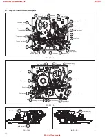
FINAL ASSEMBLY <M2>
CN5001
CN2001
CN7001
CN7105
CN7102
For JOG
CN501
1
1
OK
NG
CN
CN
CN
90
BLUE
JS3001
JS
30
01
D3
00
1
Q3
00
3
Q3
00
2
CN
50
01
"Z"
f
b
b
d'
c'
c
e
b
c'
c
h
b
b
b
d
c'
c'
d'
e
f
f
f
f
f
f
f
h
g
g
a
b
MECHANISM ASSY<M4>
510
510
510
516
532
533
533
533
517
515
516
515
d
g
e
501A
501
529 [
HR-J790EU/J795EK/J795MS]
501B
REAR SIDE
504
502
503
503
MAIN BOARD ASSY<03>
R.PAUSE BOARD ASSY<91>
[HR-J790EU/J795MS]
SAT CTL BOARD ASSY<94>
523
511
512
Insert the bushing of POWER CORD
so as not to twist the cord.
Accord the position of V gap on R. Encoder and PWB silk " ".
<Phase alignment>
Accord the position of Boss on R. Encoder and PWB silk " ".
For the prevention of the DRUM FPC damage.
When you attach the MECHA UNIT on B. CHASSIS.
Attach the MECHA UNIT after the positioning boss "z" of the
B. CHASSIS is matched to the positioning hole of the MECHA UNIT.
CN7003
WR4
To main CN7001
Front panel back side
ADV. JOG
BOARD
ASSY<38>
530
HR-J790EU/J795EK/J795MS
HR-J790EU/J795EK/J795MS
BACK SIDE
From CAPSTAN MDA
Right side
Right side
from FRONT PANEL
Right side
DRUM
A/C HEAD
NOTE
Right side
Back side
electrode side
supporting side
Except U/U(C)/JPN
1. Insert direction of FCC WIRE as follows.
2. FFC WIRE and DRUM FPC WIRE should be insert as follows.
3. Insert direction of POWER CORD.
NEUTRAL
WHITE LINE
CN5001
NEUTRAL
CN5001
U/U(C)/JPN
505
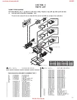
BEWARE OF BOGUS PARTS
Parts that do not meet specifications may
cause trouble in regard to safety and per-
formance. We recommend that genuine JVC
parts be used.
www.freeservicemanuals.info
25/8/2013
World of free manuals


