background image

Page 16

November 8, 2002 8:36 am

   — 16 —

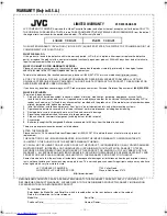
WARRANTY REPAIR / REPLACEMENT FORM

PLEASE COMPLETE THE FOLLOWING:

PLEASE NOTE: P.O. BOXES ARE NOT ACCEPTABLE

NAME:_________________________________________________________

STREET ADDRESS:______________________________________________

CITY:___________________ STATE________________ ZIPCODE ______________

DAY TIME PHONE NUMBER:_______________________________________

____________________________________________________________________________________

REASON FOR RETURN

__________________________________________

__________________________________________

__________________________________________

Please do not return your product to the retailer. Instead, please box the product carefully, preferably in the original carton,
and ship, insured to the JVC repair/replacement facility nearest you.

A COPY OF YOUR BILL OF SALE, A COMPLETED WARRANTY REPAIR/REPLACEMENT FORM AND ALL OF THE ORIGINAL
ACCESSORIES WHICH CAME WITH YOUR UNIT MUST ACCOMPANY THE PRODUCT TO BE ELIGIBLE FOR REPAIR/
REPLACEMENT UNDER WARRANTY.

To obtain the address of the location nearest you, please call (800) 537-5722 or visit our website http://www.jvc.com.

If you have any questions concerning your JVC Product, please contact our Customer Relations Department at

(800) 252-5722.

___________________________________________________________________________

FOR SERVICING (Only in U.S.A.)

HOW TO LOCATE YOUR JVC SERVICE CENTER

JVC SERVICE & ENGINEERING

COMPANY OF AMERICA

ACCESSORIES

Don’t service the product yourself.

TOLL FREE: 1-800-537-5722

http://www.jvc.com

Dear Customer,

In order to receive the most satisfaction from your purchase, please read the instruction booklet before operating the
unit. In the event that repair is necessary, or for the address nearest your location within the Continental United States,
please call 1-800-537-5722 for your nearest authorized servicer or visit our website at www.JVC.com. Remember to
retain your Bill of Sale for Warranty Service.

— JVC

DIVISION OF JVC AMERICAS CORP.

Sophisticated electronic products may require occasional service. Just as quality is a keyword in the engineering and
production of the wide array of JVC products, service is the key to maintaining the high level performance for which JVC
is world famous. The JVC service and engineering organization stands behind our products.

NATIONAL HEADQUARTERS

JVC SERVICE & ENGINEERING COMPANY OF AMERICA

DIVISION OF JVC AMERICAS CORP.

10 New Maple Avenue

Pine Brook, NJ 07058-9641

To purchase accessories for your JVC product, you
may contact your local JVC Dealer.
From the 48 Continental United States call toll free:
1-800-882-2345 or on the web at www.JVC.com

CAUTION

To prevent electrical shock, do not open the cabinet.
There are no user serviceable parts inside.
Please refer to qualified service personnel for repairs.

HR-S2902U-EN-1.fm Page 16 Friday, November 8, 2002 8:37 AM

Summary of Contents for HR-S2902U

Page 1: ...pment This equipment has been tested and found to comply with the limits for a Class B digital device pursuant to Part 15 of the FCC Rules These limits are designed to provide reasonable protection against harmful interference in a residential installation This equipment generates uses and can radiate radio frequency energy and if not installed and used in accordance with the instructions may caus...

Page 2: ...verloading Do not overload wall outlets extension cords or integral convenience receptacles as this can result in a risk of fire or electric shock 4 Power Cord Protection Power supply cords should be routed so that they are not likely to be walked on or pinched by items placed upon or against them paying particular attention to cords at plugs convenience receptacles and the point where they exit f...

Page 3: ...require extensive work by a qualified technician to restore the product to its normal operation e If the product has been dropped or damaged in anyway f When the product exhibits a distinct change in performance this indicates a need for service 3 Replacement Parts When replacement parts are required be sure the service technician has used replacement parts specified by the manufacturer or which h...

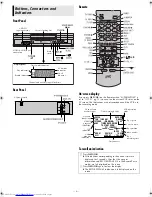
Page 4: ... connector S VIDEO AC power cord A Press OSD OK All indications corresponding to the current status are displayed for 5 seconds After that the counter information and RECORD PAUSE if in the RecordPause mode are left displayed on the screen B Press OSD OK again to clear the display The RECORD PAUSE indication is left displayed on the screen TIMER CANCEL B E CH125 RECORD THU 12 00 AM PAUSE STEREO WA...

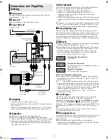
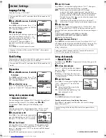
Page 5: ... on areas or reception conditions the VCR may not receive the Auto clock setting data from a PBS channel If this function is taking a considerable amount of time it may be necessary to perform the procedure in Semiauto Clock Set 墌 pg 6 or Manual Clock Set 墌 pg 6 What to do if Plug Play setting failed If an incorrect time is displayed on the display panel perform the procedure in Semiauto Clock Set...

Page 6: ...in step 4 ON Adjustment will be made by the built in clock itself OFF Select when Daylight Saving Time does not apply to you D Select time zone Press OK or e to move the highlight bar to TIME ZONE then press rt repeatedly until AUTO or the desired time zone is selected Each time you press the button the time zone changes as follows AUTO ATLANTIC EASTERN CENTRAL MOUNTAIN PACIFIC ALASKA HAWAII back ...

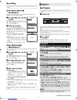
Page 7: ...R Do not apply too much pressure when inserting The VCR turns on and the counter on the on screen display is reset automatically If the cassette s record safety tab has been removed playback begins automatically B Start playback Press PLAY 4 The S VHS indicator lights up when you play back a tape recorded in S VHS mode or in S VHS ET mode 墌 pg 9 Turn on the VCR and TV and select the VCR channel or...

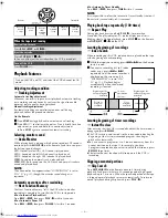
Page 8: ...an 5 seconds The play indicator on the display panel starts blinking slowly To stop playback press STOP 8 on the Remote or STOP EJECT 0 on the VCR Locating beginning of recordings Index Search When recording on this VCR index codes are placed on the tape at the beginning of each recording A While the tape is not running press 2or 6on the Remote to start search B To access a recording of 2 to 9 ind...

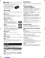
Page 9: ...lay panel starts blinking Each time you press the button recording length increases in 30 minute intervals up to 6 hours The VCR shuts off after recording is finished To cancel an ITR press STOP 8 on the Remote or STOP EJECT 0 on the VCR Watching one program while recording another During recording If you connect the TV and the VCR only using the RF connection 墌 pg 5 to view pictures from the VCR ...

Page 10: ...ss PROG CHECK C Access Program screen Press PROG CHECK again Each time you press PROG CHECK the next program s Program screen appears D Cancel or change program setting To cancel a program press CANCEL when the Program screen you do not want is shown To change a program press the appropriate button START Number key 1 and or 4 STOP Number key 2 and or 5 DATE Number key 3 and or 6 CH DAILY M F Numbe...

Page 11: ...s is recommended for S VHS ET recordings On some tapes picture quality will not improve even if the S VHS ET function is used Check the recording quality before you start important recordings 䡵 VIDEO CALIBRATION ON OFF When this function is set to ON this VCR checks the condition of the tape in use during playback and recording and compensates to provide the highest possible pictures This takes pl...

Page 12: ...ck a prerecorded tape containing two separate audio programs on the Hi Fi tracks you can choose either one by selecting either HI FI L or HI FI R HI FI Normally select this Hi Fi sound is played back HI FI L Sound on the left Hi Fi channel is played back HI FI R Sound on the right Hi Fi channel is played back NORM Sound on the normal track is played back MIX Both sounds on the Hi Fi track and norm...

Page 13: ...Set the edit mode to ON for the VCRs if such a mode is equipped On this VCR set PICTURE CONTROL to EDIT 墌 pg 11 F Start playback Press PLAY 4 on the playback VCR G Start recording Press REC 7 on the recording VCR Editing To audio video input This VCR Another VCR To AUDIO VIDEO IN To AUDIO VIDEO OUT To audio video output When using this VCR as the recording VCR connect this VCR s AUDIO VIDEO IN con...

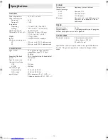
Page 14: ...SC type color signal and EIA monochrome signal 525 lines 60 fields Recording Playback system DA 4 Double Azimuth head helical scan system Signal to noise ratio 45 dB Horizontal resolution VHS 230 lines S VHS 400 lines Frequency range Normal audio 70 Hz to 10 000 Hz Hi Fi audio 20 Hz to 20 000 Hz Input Output RCA connectors IN x 1 OUT x 1 S video connectors IN x 1 OUT x 1 TUNER Tuning system Freque...

Page 15: ...o any attachment not provided with the products or if the model or serial number has been altered tampered with defaced or removed 2 Initial installation installation and removal from built in entertainment centers and other mounting systems 3 Operational adjustments covered in the Owner s Manual normal maintenance including head cleaning 4 Damage that occurs in shipment due to act of God and cosm...

Page 16: ..._________________________________ FOR SERVICING Only in U S A HOW TO LOCATE YOUR JVC SERVICE CENTER JVC SERVICE ENGINEERING COMPANY OF AMERICA ACCESSORIES Don t service the product yourself TOLL FREE 1 800 537 5722 http www jvc com Dear Customer In order to receive the most satisfaction from your purchase please read the instruction booklet before operating the unit In the event that repair is nec...

Reviews: