background image

— 2 —

Page 2

November 8, 2002 8:36 am

Failure to heed the following precautions may result in damage to 
the VCR, Remote or video cassette.

1. DO NOT place the VCR . . .

...in an environment prone to extreme temperatures or 
humidity.
...in direct sunlight.
...in a dusty environment.
...in an environment where strong magnetic fields are 
generated.
...on a surface that is unstable or subject to vibration.

2. DO NOT block the VCR’s ventilation openings.
3. DO NOT place heavy objects on the VCR or on the Remote.
4. DO NOT place anything which might spill on the top of the 

VCR or on the Remote.

5. AVOID violent shocks to the VCR during transport.

Cassettes marked “S-VHS” and “VHS” can be used with this 
video cassette recorder. However, S-VHS recordings are 
possible only with cassettes marked “S-VHS”. 
By using S-VHS ET it is possible to record and play back with 
S-VHS picture quality on VHS cassettes with this VCR.

As an E

NERGY

 S

TAR

®

 Partner, JVC has determined that this product 

or product model meets the E

NERGY

 S

TAR

®

 guidelines for energy 

efficiency.

IMPORTANT PRODUCT SAFETY 

INSTRUCTIONS

Electrical energy can perform many useful functions. But improper 
use can result in potential electrical shock or fire hazards. This 
product has been engineered and manufactured to assure your 
personal safety. In order not to defeat the built-in safeguards, 
observe the following basic rules for its installation, use and 
servicing.

ATTENTION:

Follow and obey all warnings and instructions marked on your 
product and its operating instructions. For your safety, please read 
all the safety and operating instructions before you operate this 
product and keep this booklet for future reference.

INSTALLATION

1. Grounding or Polarization

(A) Your product may be equipped with a polarized alternating-

current line plug (a plug having one blade wider than the 
other). This plug will fit into the power outlet only one way. 
This is a safety feature.
If you are unable to insert the plug fully into the outlet, try 
reversing the plug. If the plug should still fail to fit, contact your 
electrician to replace your obsolete outlet. Do not defeat the 
safety purpose of the polarized plug.

(B) Your product may be equipped with a 3-wire grounding-type 

plug, a plug having a third (grounding) pin. This plug will only 
fit into a grounding-type power outlet. This is a safety feature.
If you are unable to insert the plug into the outlet, contact your 
electrician to replace your obsolete outlet. Do not defeat the 
safety purpose of the grounding-type plug.

2. Power Sources

Operate your product only from the type of power source 
indicated on the marking label. If you are not sure of the type of 
power supply to your home, consult your product dealer or local 
power company. If your product is intended to operate from 
battery power, or other sources, refer to the operating instructions.

3. Overloading

Do not overload wall outlets, extension cords, or integral 
convenience receptacles as this can result in a risk of fire or 
electric shock.

4. Power Cord Protection

Power supply cords should be routed so that they are not likely to 
be walked on or pinched by items placed upon or against them, 
paying particular attention to cords at plugs, convenience 
receptacles, and the point where they exit from the product.

5. Ventilation

Slots and openings in the cabinet are provided for ventilation. To 
ensure reliable operation of the product and to protect it from 
overheating, these openings must not be blocked or covered.

Do not block the openings by placing the product on a bed, 
sofa, rug or other similar surface.

Do not place the product in a built-in installation such as a 
bookcase or rack unless proper ventilation is provided or the 
manufacturer’s instructions have been adhered to.

6. Wall or Ceiling Mounting

The product should be mounted to a wall or ceiling only as 
recommended by the manufacturer.

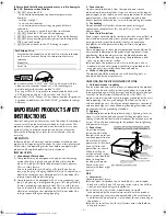
ANTENNA INSTALLATION INSTRUCTIONS

1. Outdoor Antenna Grounding

If an outside antenna or cable system is connected to the product, 
be sure the antenna or cable system is grounded so as to provide 
some protection against voltage surges and built-up static charges. 
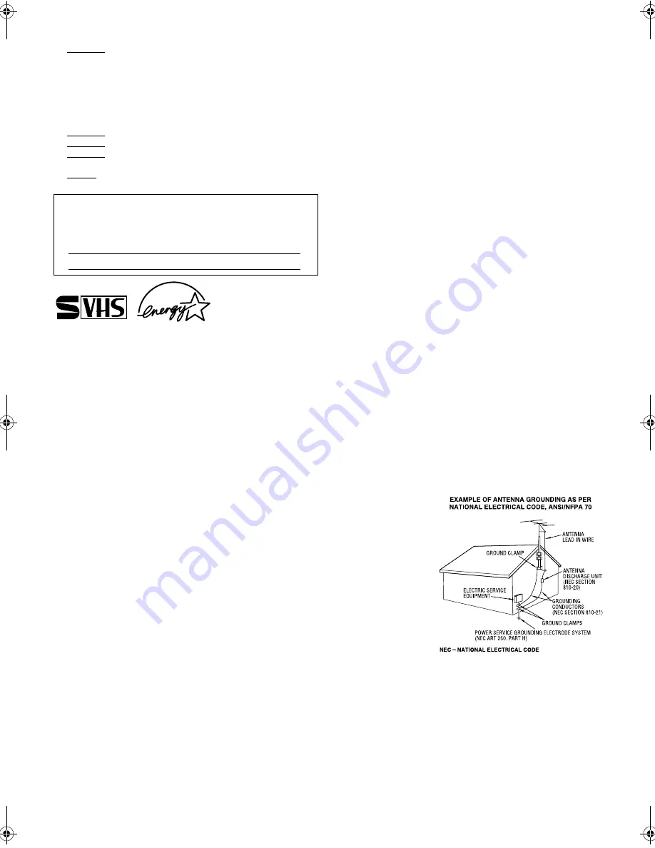
Article 810 of the National Electrical Code, ANSI/NFPA 70, 
provides information with regard to proper grounding of the mast 
and supporting structure, grounding of the lead-in wire to an 
antenna discharge unit, size of grounding connectors, location of 
antenna discharge unit, connection to grounding electrodes, and 
requirements for the grounding electrode.

2. Lightning

For added protection for this product during a lightning storm, or 
when it is left unattended and unused for long periods of time, 
unplug it from the wall outlet and disconnect the antenna or cable 
system. This will prevent damage to the product due to lightning 
and power-line surges.

3. Power Lines

An outside antenna 
system should not be 
located in the vicinity of 
overhead power lines or 
other electric light or 
power circuits, or where 
it can fall into such 
power lines or circuits. 
When installing an 
outside antenna system, 
extreme care should be 
taken to keep from 
touching such power 
lines or circuits as 
contact with them might 
be fatal.

USE

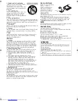
1. Accessories

To avoid personal injury:

Do not place this product on an unstable cart, stand, tripod, 
bracket, or table. It may fall, causing serious injury to a child or 
adult, and serious damage to the product.

Use only with a cart, stand, tripod, bracket, or table 
recommended by the manufacturer or sold with the product.

Use a mounting accessory recommended by the manufacturer 
and follow the manufacturer’s instructions for any mounting of 
the product.

Do not try to roll a cart with small casters across thresholds or 
deep-pile carpets.

For Customer Use:

Enter below the Model No. and Serial No. which are located 
on the rear of cabinet. Retain this information for future 
reference.
Model No.

Serial No.

HR-S2902U-EN-1.fm Page 2 Friday, November 8, 2002 8:37 AM

Summary of Contents for HR-S2902U

Page 1: ...pment This equipment has been tested and found to comply with the limits for a Class B digital device pursuant to Part 15 of the FCC Rules These limits are designed to provide reasonable protection against harmful interference in a residential installation This equipment generates uses and can radiate radio frequency energy and if not installed and used in accordance with the instructions may caus...

Page 2: ...verloading Do not overload wall outlets extension cords or integral convenience receptacles as this can result in a risk of fire or electric shock 4 Power Cord Protection Power supply cords should be routed so that they are not likely to be walked on or pinched by items placed upon or against them paying particular attention to cords at plugs convenience receptacles and the point where they exit f...

Page 3: ...require extensive work by a qualified technician to restore the product to its normal operation e If the product has been dropped or damaged in anyway f When the product exhibits a distinct change in performance this indicates a need for service 3 Replacement Parts When replacement parts are required be sure the service technician has used replacement parts specified by the manufacturer or which h...

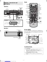
Page 4: ... connector S VIDEO AC power cord A Press OSD OK All indications corresponding to the current status are displayed for 5 seconds After that the counter information and RECORD PAUSE if in the RecordPause mode are left displayed on the screen B Press OSD OK again to clear the display The RECORD PAUSE indication is left displayed on the screen TIMER CANCEL B E CH125 RECORD THU 12 00 AM PAUSE STEREO WA...

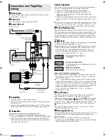
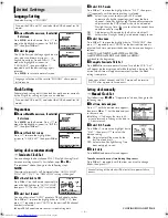
Page 5: ... on areas or reception conditions the VCR may not receive the Auto clock setting data from a PBS channel If this function is taking a considerable amount of time it may be necessary to perform the procedure in Semiauto Clock Set 墌 pg 6 or Manual Clock Set 墌 pg 6 What to do if Plug Play setting failed If an incorrect time is displayed on the display panel perform the procedure in Semiauto Clock Set...

Page 6: ...in step 4 ON Adjustment will be made by the built in clock itself OFF Select when Daylight Saving Time does not apply to you D Select time zone Press OK or e to move the highlight bar to TIME ZONE then press rt repeatedly until AUTO or the desired time zone is selected Each time you press the button the time zone changes as follows AUTO ATLANTIC EASTERN CENTRAL MOUNTAIN PACIFIC ALASKA HAWAII back ...

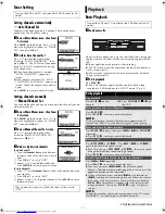
Page 7: ...R Do not apply too much pressure when inserting The VCR turns on and the counter on the on screen display is reset automatically If the cassette s record safety tab has been removed playback begins automatically B Start playback Press PLAY 4 The S VHS indicator lights up when you play back a tape recorded in S VHS mode or in S VHS ET mode 墌 pg 9 Turn on the VCR and TV and select the VCR channel or...

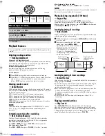
Page 8: ...an 5 seconds The play indicator on the display panel starts blinking slowly To stop playback press STOP 8 on the Remote or STOP EJECT 0 on the VCR Locating beginning of recordings Index Search When recording on this VCR index codes are placed on the tape at the beginning of each recording A While the tape is not running press 2or 6on the Remote to start search B To access a recording of 2 to 9 ind...

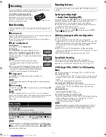
Page 9: ...lay panel starts blinking Each time you press the button recording length increases in 30 minute intervals up to 6 hours The VCR shuts off after recording is finished To cancel an ITR press STOP 8 on the Remote or STOP EJECT 0 on the VCR Watching one program while recording another During recording If you connect the TV and the VCR only using the RF connection 墌 pg 5 to view pictures from the VCR ...

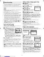
Page 10: ...ss PROG CHECK C Access Program screen Press PROG CHECK again Each time you press PROG CHECK the next program s Program screen appears D Cancel or change program setting To cancel a program press CANCEL when the Program screen you do not want is shown To change a program press the appropriate button START Number key 1 and or 4 STOP Number key 2 and or 5 DATE Number key 3 and or 6 CH DAILY M F Numbe...

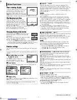
Page 11: ...s is recommended for S VHS ET recordings On some tapes picture quality will not improve even if the S VHS ET function is used Check the recording quality before you start important recordings 䡵 VIDEO CALIBRATION ON OFF When this function is set to ON this VCR checks the condition of the tape in use during playback and recording and compensates to provide the highest possible pictures This takes pl...

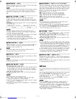
Page 12: ...ck a prerecorded tape containing two separate audio programs on the Hi Fi tracks you can choose either one by selecting either HI FI L or HI FI R HI FI Normally select this Hi Fi sound is played back HI FI L Sound on the left Hi Fi channel is played back HI FI R Sound on the right Hi Fi channel is played back NORM Sound on the normal track is played back MIX Both sounds on the Hi Fi track and norm...

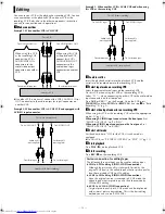
Page 13: ...Set the edit mode to ON for the VCRs if such a mode is equipped On this VCR set PICTURE CONTROL to EDIT 墌 pg 11 F Start playback Press PLAY 4 on the playback VCR G Start recording Press REC 7 on the recording VCR Editing To audio video input This VCR Another VCR To AUDIO VIDEO IN To AUDIO VIDEO OUT To audio video output When using this VCR as the recording VCR connect this VCR s AUDIO VIDEO IN con...

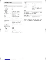
Page 14: ...SC type color signal and EIA monochrome signal 525 lines 60 fields Recording Playback system DA 4 Double Azimuth head helical scan system Signal to noise ratio 45 dB Horizontal resolution VHS 230 lines S VHS 400 lines Frequency range Normal audio 70 Hz to 10 000 Hz Hi Fi audio 20 Hz to 20 000 Hz Input Output RCA connectors IN x 1 OUT x 1 S video connectors IN x 1 OUT x 1 TUNER Tuning system Freque...

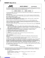
Page 15: ...o any attachment not provided with the products or if the model or serial number has been altered tampered with defaced or removed 2 Initial installation installation and removal from built in entertainment centers and other mounting systems 3 Operational adjustments covered in the Owner s Manual normal maintenance including head cleaning 4 Damage that occurs in shipment due to act of God and cosm...

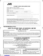
Page 16: ..._________________________________ FOR SERVICING Only in U S A HOW TO LOCATE YOUR JVC SERVICE CENTER JVC SERVICE ENGINEERING COMPANY OF AMERICA ACCESSORIES Don t service the product yourself TOLL FREE 1 800 537 5722 http www jvc com Dear Customer In order to receive the most satisfaction from your purchase please read the instruction booklet before operating the unit In the event that repair is nec...

Reviews: