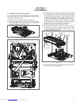
1-3
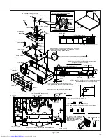
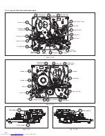
Fig. 1-2-2d
1
1
A
FW
71
04
FW
71
07
1
1
B
Fig.1
b
b
b
z
z
JS3001
D3001
Q3001
CN
50
01
b
Q3002
CN1
c
d
JS3001
c
d
e
e
REAR SIDE
Must confirm soldering condition as no soldering and dry soldering
at portion of Power cord lead on Main board assembly before atta-
ch Main board assembly to Bottom chassis.
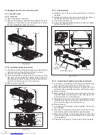
Hang the hook of the Terminal board
in hole of Bottom chassis.
Accord the position of V gap on R. Encoder and PWB silk " ".
Accord the position of Boss on R. Encoder and PWB silk " ".
Slot to fit at (L3a) of the Bottom chassis.
Drum
Drum shield
Screw(S3f)
Mechanism
assembly
FE head
Pole base
(Supply)
Pole base
(Take up)
(S1a)
(S2a)
(WR3a)
<Note 2a>
(S3a)
<Note 3a>
(S3f)
(S3b)
<Note 3a>
(S3c)
<Note 3c>
(S3d)
<Note 3c>
(S3e)
<Note 3c>
(S2a)
(L1a)
(L4c)
(L1a)
NOTE) Hang the hook of the Top cover
in hold of Bottom chassis.
[1] Top cover
[3] Drum shield
[4] Rear S Jack
board assembly
[4] Main board
assembly
Bottom chassis
[2] Front panel
assembly
<Note 2b>
Cassette door
<Note 2b>
[2] Knob assembly
(S2c)
Switch lever
<Note 2b>
(S2b)
(WR2a)
<Note 2a>
(WR2b)
<Note 2a>
[3] Mechanism
assembly
<Note 3b>
[2] Front S Jack
board assembly
[2] Adv. Jog/SW board assembly
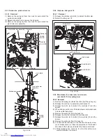
NOTE) When you fix S Jack board assembly with the screw,
put jig under Front panel assembly.
NOTE) Insert FFC wire to the connector before attaching
Adv. Jog/SW board assembly to Front panel assembly.
back side
back side
20mm
NOTE) 1. Insert FFC wire to the connector before attaching Front
S Jack board assembly to Front panel assembly.
2. Fig. 1 reference
30mm
60mm
Back side of Front panel assembly
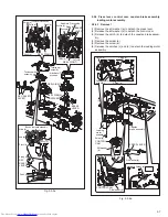
NOTE) After screwing,execute the
adjustment inspection of the tape running.
Absorb the looseness the wire in the
S Jack side.
from Capstan MDA board assembly
right side
right side
(WR3b)
<Note 2a>
(L4a)
Power cord should not be touch to
the VA5001 and C5001.
WHITE
LINE
NOTE
1. Insert direction of FFC WIRE as follows.
electrode side
supporting side
right side
back side
2. FFC WIRE and DRUM FPC WIRE should be insert as follows.
CN
OK
CN
CN
NG
90
°
DETAIL " A "
DETAIL " B "
CN7103
2D DIGITAL
•
The wire of FW3001 or FW3002
should not approach the moving
parts of Mechanism assembly.
•
Absurb the looseness of the wire
on the Tuner side.
Bend the wire by the root.
from Adv. Jog/SW
board assembly
from Front S Jack
board assembly
Hang the hook of Bottom chassis on the Main board assembly.
CN7103
FW7104
FW7107
CN2001
VR2251
WHITE
LINE
VA5001
C5001
CN7001
C903
right side
back side
.
Power cord arrangement should be following drawing.
[3] Drum assembly
<Note 3c>
Switch knob
<Note 2b>
(L4b)
(L3a)
(L2a)
(L2a)
(L2b)
(L2b)
FW3002
FW3001


