background image

SERVICE MANUAL

No. 82807

June 2000

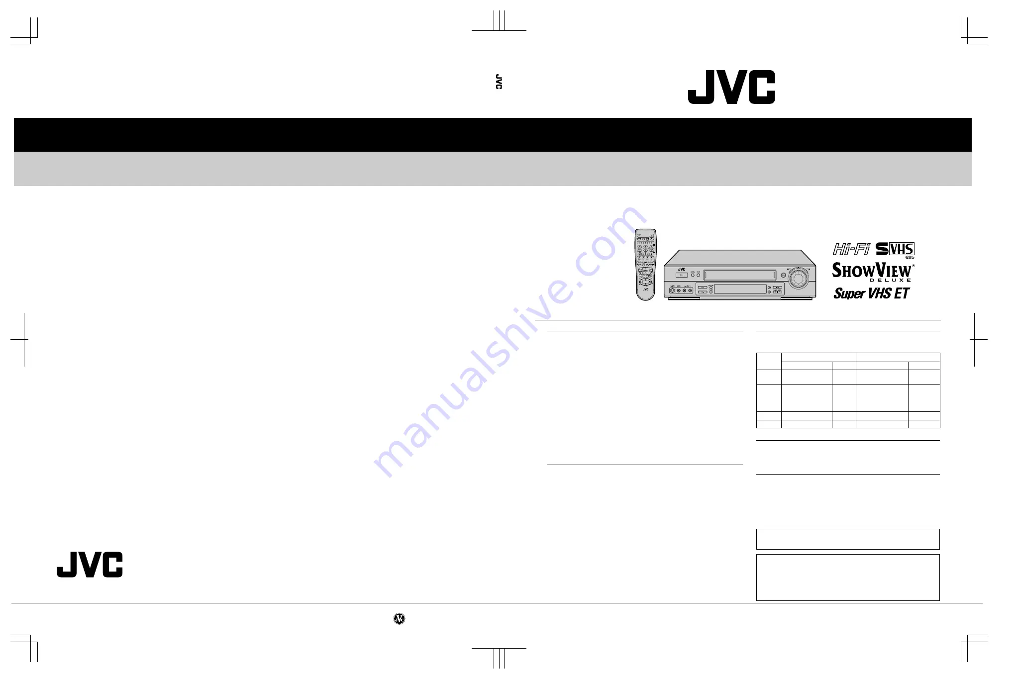
HR-S6700MS/S7700MS

CARACTERISTIQUES TECHNIQUES 

(The specifications shown pertain specifically to the model HR-S7700MS)

MAGNETOSCOPE

Printed in Japan

VICTOR COMPANY OF JAPAN, LIMITED
VIDEO DIVISION

S40894

This service manual is printed on 100% recycled paper.

COPYRIGHT © 2000 VICTOR COMPANY OF JAPAN, LTD.

HR-S6700MS/S7700MS

No. 82807

GÉNÉRALES

Alimentation

: CA 220 V – 240 V 

`

 , 50 Hz/60 Hz

Consommation

Alimentation en marche : 25 W
Alimentation en veille

: 4,7 W

Températures
Fonctionnement

: 5°C à 40°C

Stockage

: -20°C à 60°C

Position de fonctionnement

: Seulement horizontale

Dimensions (LxHxP)

: 400 mm x 94 mm x 344 mm

Poids

: 4,3 kg

Format

: Standard S-VHS/VHS PAL/SECAM

Largeur de bande

: 12,65 mm

Vitesse de bande

(VN)

: 23,39 mm/s

(LD)

: 11,70 mm/s

Durée maximale d’enregistrement

(VN)

: 240 mn avec une cassette vidéo E-240

(LD)

: 480 mn avec une cassette vidéo E-240

VIDÉO/AUDIO

Système de signal

: Signaux couleur PAL/SECAM et signal

monochrome CCIR, 625 lignes/50 trames

Système d’enregistrement

: Balayage hélicoïdal DA4 (Double Azimuth)

Entrée

: 0,5 Vcc à 2,0 Vcc, 75 ohms, asymétrique

Sortie

: 1,0 Vcc, 75 ohms, asymétrique

Rapport signal/bruit

: 45 dB

Résolution horizontale : 400 lignes (S-VHS-PAL)

250 lignes (VHS-PAL)
240 lignes (VHS-SECAM)

Gamme de fréquence

: 70 Hz à 10.000 Hz (Audio normal)

20 Hz à 20.000 Hz (Audio Hi-Fi)

Entrée/sortie

: Connecteurs péritélévision à 21 broches :

  ENTREE/SORTIE x 1, ENTREE/DECODEUR x 1
Connecteurs RCA:
  ENTREE VIDEO x 1,
  ENTREE AUDIO x 1,
  SORTIE AUDIO x 1
Connecteurs S-Vidéo:
  ENTREE x 1, SORTIE x 1

SYNTONISEUR

Système de syntonisation

: Syntoniseur à synthèse de fréquence

Capacité de canaux TV

: 99 positions (+ position AUX)

Canaux couverts

MINUTERIE

Référence de l’horloge

: Par quartz

Capacité de programmation : Minuterie sur 1 an/8 programmes
Durée de soutien mémoire : 60 mn

ACCESSOIRES

Accessoires fournis

: Câble RF,

Câble péritélévision à 21 broches,
Adaptateur antenne,
Contrôleur satellite RM-SD1,
Boîtier de télécommande à infrarouge,
Pile “R6” x 2,
Etiquettes S-VHS ET

ATTENTION:

Ce magnétoscope contient des microprocesseurs. Des bruits
électroniques externes ou des interférences peuvent causer un mauvais
fonctionnement. Dans de tels cas, couper l’alimentation et débrancher
le cordon d’alimentation. Puis le rebrancher et remettre l’alimentation.
Sortir la cassette. Après contrôle de la cassette, faire fonctionner
l’appareil comme d’ordinaire.

Les caractéristiques techniques sont pour le mode VN à moins

d’indication contraire.

Présentation et caractéristiques modifiables sans préavis.

Gamme

SECAM L

PAL B/G

       Fréquence

Canaux        Fréquence

   Canaux

VHF

49 MHz – 65 MHz 2 – 4

47 MHz – 89 MHz

E2 – E4

(LOW)

X, Y, Z
E5 – E12

VHF

104 MHz

5 – 10

104 MHz

S1 – S20

(HIGH)   – 300 MHz

CATV

  – 300 MHz

M1 – M10
U1 – U10

Hyper

300 MHz – 470 MHz CATV

302 MHz – 470 MHz S21 – S41

UHF

470 MHz – 862 MHz 21 – 69 470 MHz – 862 MHz E21 – E69

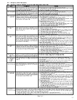
Summary of Contents for HR-S6700MS

Page 1: ...000 Hz Audio Hi Fi Entrée sortie Connecteurs péritélévision à 21 broches ENTREE SORTIE x 1 ENTREE DECODEUR x 1 Connecteurs RCA ENTREE VIDEO x 1 ENTREE AUDIO x 1 SORTIE AUDIO x 1 Connecteurs S Vidéo ENTREE x 1 SORTIE x 1 SYNTONISEUR Système de syntonisation Syntoniseur à synthèse de fréquence Capacité de canaux TV 99 positions position AUX Canaux couverts MINUTERIE Référence de l horloge Par quartz...

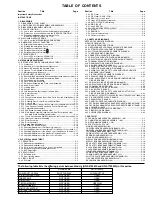
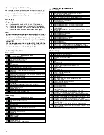
Page 2: ... CIRCUIT 3 2 3 3 1 D A level 3 2 TABLE OF CONTENTS Section Title Page Section Title Page 3 3 2 EE Y level 3 3 3 3 3 PB Y level S VHS VHS 3 3 3 3 4 REC color colour level 3 3 3 3 5 Video EQ Frequency response 3 4 3 3 6 AUTO PICTURE initial setting 3 4 3 4 AUDIO CIRCUIT 3 5 3 4 1 Audio REC FM 3 5 3 5 PAL SECAM CONVERTER CIRCUIT 3 5 3 5 1 fH VCO 3 5 3 5 2 DEMOD Fo 3 5 3 5 3 Colour difference level 3 ...

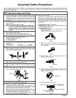
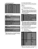
Page 3: ...e specified for compli ance with recognized codes pertaining to X ray emission Consequently when servicing these products replace the cath ode ray tubes and other parts with only the specified parts Under no circumstances attempt to modify these circuits Unauthorized modification can increase the high voltage value and cause X ray emission from the cathode ray tube 12 Crimp type wire connector In ...

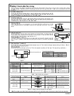
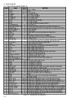
Page 4: ... between terminals and surrounding metallic parts See table 1 below 4 Leakage current test Confirm specified or lower leakage current between earth ground power cord plug prongs and externally exposed accessible parts RF terminals antenna terminals video and audio input and output terminals microphone jacks earphone jacks etc Measuring Method Power ON Insert load Z between earth ground power cord ...

Page 5: ......

Page 6: ...mbly D3001 LED Q3002 Start sensor Q3003 End sensor S3002 S cassette switch Note 5b The wire WR5 has excess length that may be loose as it is quite long After inserting the wire and connectors the loose portion of the wire should be taken up and accommodated be tween the A C head base and the main deck Note 6 The REC safety board assembly is attached to the SW Display board assembly It is therefore...

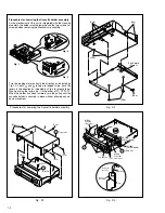
Page 7: ...ading motor pulley in the direction as indicated by Fig 2 As both Å and ı levers are lodged twice push the levers in the direction as indicated by Fig 3 to release them When pushing the levers do it in the order of Å ı ı Å When the holder has been lowered turn the pulley until the cassette holder is securely in place without allowing any up down movement Procedures for Lowering the Cassette holder...

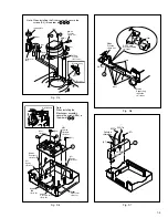
Page 8: ...5a Note 5a 5 L5 Spacer Note 5a L5 Spacer Note 5a Q3003 End sensor Note 5a Q3002 Start sensor Note 5a D3001 LED Note 5a S3002 S cassette switch Note 5a WR5 Foil side Note3a Note 5b A C head base WR5 CN1 a b Note When installing the Mechanism assembly secure the screws S5a in the order of a b L6c CN7001 L6b 6 CN7191 L6a REC Safety board assembly Note 6 WR6b Foil side Note 3a WR6a Supporting tape sid...

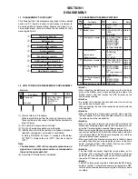
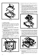
Page 9: ...g the edge of the Main board assembly and remove the Main board and Mecha nism assemblies together At this stage be careful of the power cord and prongs of the jacks on the back side Re fer to Fig 1 4 2 8 Remove the SW Display board assembly and REC safety board assembly Refer to page 1 3 of 1 3 DISASSEM BLY ASSEMBLY METHOD Take care not to pull the flat wires Fig D7 from CN7001 and CN7191 G Fig D...

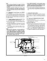
Page 10: ... 4 Press the POWER button 5 With lock levers Åı on the left and right of the Cassette holder assembly pulled toward the front slide the holder in the same direction as the cassette insertion direction For the positions of lock levers Åı refer to the Pro cedures for Lowering the Cassette holder assembly on pages 1 2 of 1 3 DISASSEMBLY ASSEMBLY METHOD 6 The cassette holder lowers and when the loadin...

Page 11: ...ment of emer gency 3 Mechanism sensor information at the moment of emergency 4 Mechanism mode position at the moment of emer gency Note For the emergency detail information 1 see 1 6 4 Emer gency detail information 1 3 Transmit the code 59 from the Jig RCU once again The FDP shows the emergency detail information 2 in the form of 5 6 7 5 Type of the cassette tape in use 1 6 Winding position of the...

Page 12: ...ue Housing load increasing factors Temperature environment low tempera ture etc mechanism wear or failure 3 The sensor switch for detecting the end of ejection are not functioning normally 4 The loading motor drive voltage is lower than specified or power is not sup plied to the motor MDA 5 When the user attempted to eject a cassette a foreign object or perhaps the user s hand was caught in the op...

Page 13: ...compression OFF as a result of POWER OFF 16 Mode transition to STOP with pinch roller compression ON as a result of POWER ON 18 Mode transition to PLAY 1A Mode transition to FWD SEARCH 1C Mode transition to REC 1E Mode transition to FWD STILL SLOW 20 Mode transition to REV STILL SLOW 22 Mode transition to REV SEARCH 24 Mode transition from FF REW to STOP 26 Mode transition to FF 28 Mode transition...

Page 14: ...tape TC 40 0D 0F Small reel thick tape T 40 11 14 Small reel thick tape T 60 15 18 Small reel thick tape T 80 DF 160 17 1A Small reel thick tape T 80 DF 180 19 1D Small reel thick tape T 100 1D 21 Small reel thick tape T 120 DF 240 1E 1F Small reel thin tape T 140 1F 23 Small reel thick tape T 130 21 23 Small reel thin tape T 160 21 23 Small reel thin tape T 168 22 24 Small reel thick tape DF 300 ...

Page 15: ...ROL SIGNAL FOR TV LINK 32 R PAUSE COMPU_IN IN REMOTE PAUSE CONTROL HR S7700MS NC 33 RAE_OUT COMPUOUT NC 34 P50_OUT OUT CONTROL SIGNAL FOR TV LINK 35 LMC1 OUT LOADING MOTOR DRIVE 1 36 LMC2 OUT LOADING MOTOR DRIVE 2 37 LMC3 OUT LOADING MOTOR DRIVE 3 38 SB_G PWM OUT VOLTAGE CONTROL SIGNAL FOR VIDEO FREQUENCY RESPONSE 39 STB TEST OUT STROBE SIGNAL FOR FDP DRIVER 40 POWER_DET IN DETECTION SIGNAL FOR PO...

Page 16: ...OUT MEMORY TIMING CONTROL IN THE SLOW MODE HR S7700MS 84 VSS GND 85 SP_SHORT H OUT MODE SELECT HR S6700MS 86 LP_SHORT H OUT MODE SELECT HR S6700MS 87 FLY_ON H OUT FLYING ERASE ON H HR S7700MS 88 H REC_ST H OUT HIFI AUDIO SOUND RECORDING START 89 TRICK H M_TRICK L NC 90 HEAD_SEL IN HEAD SELECT LP HEAD H SP HEAD L 91 OSD_CS OUT CHIP SELECT FOR THE ON SCREEN IC 92 SYNC_DET H IN DETECTION OF VIDEO SYN...

Page 17: ...failures If you cannot remove the cassette tape which is loaded be cause of any electrical failure manually remove it by taking the following steps 1 Unplug the power cable and remove the top cover bracket and front panel assembly See 1 3 DISASSEM BLY ASSEMBLY METHOD 2 Unload the cassette by manually turning the loading mo tor of the mechanism assembly toward the front In do ing so hold the tape b...

Page 18: ...Fig 2 1 3d 4 In the same way as in the electrical failure instructions in 2 1 3 1 4 remove the top guide 5 Raise the cassette tape cover By keeping it in that posi tion draw out the cassette tape case from the cassette holder and take out the tape 6 By hanging the pinch roller arm assembly spring back on the hook take up the slack of the tape into the cas sette Fig 2 1 3d Fig 2 1 3c Pole base asse...

Page 19: ... guard Press lever assembly Lid guide Guide arm assembly Reel disk take up side Sub brake assembly take up side Main brake assembly take up side Idler arm assembly Idler lever Main brake assembly supply side Reel disk supply side Rec safety lever Tension brake assembly Adjust pin Tension arm assembly Pole base assembly supply side Full erase head Pole base assembly take up side T1 T26 T25 T24 T23 ...

Page 20: ...y as this will cause damage to the video head 2 To clean the parts of the tape transport system other than the upper drum use a piece of closely woven cloth or a cotton swab soaked with alcohol 3 After cleaning make sure that the cleaned parts are com pletely dry before using the video tape 3 Lubrication With no need for periodical lubrication you have only to lu bricate new parts after replacemen...

Page 21: ...otary encoder B 1 2 2 11 Clutch unit B 1 2 2 12 Change lever assembly B 3 2 2 12 Direct gear B 4 2 2 12 Clutch gear B 5 2 2 12 Coupling gear 2 B 6 2 2 13 Link lever B 1 2 2 14 Cassette gear B 2 2 2 14 Control cam B 2 2 2 14 Worm gear B 1 Lid guide T B 5 2 2 15Control bracket1 B 1 2 2 15Control plate B 6 2 2 16Loading arm gear supply side B 7 2 2 16Loadingarmgear take upside B 8 2 2 16Loading arm g...

Page 22: ...ration in response to phases of the rotary encoder internal switch positions the mechanism may not operate properly unless such parts as the rotary encoder control plate loading arm gear control cam cassette gear limit gear relay gear and drive gear are installed in their correct posi tions Especially this model is not provided with any cassette hous ing assembly so that cassette loading and unloa...

Page 23: ...y into the groove See Fig 2 2 3g 4 While swinging the lock lever R of the cassette holder assembly toward the front put the legs Å and ı into the rail See Fig 2 2 3g 5 Drop the three legs on the left side of the cassette holder assembly into the groove at one time See Fig 2 2 3h 6 Slide the whole cassette holder assembly toward the front to bring it to the eject end position 7 Install the limit ge...

Page 24: ...the audio control head remove the three screws B while controlling the compression spring Fig 2 2 6a Fig 2 2 6c Fig 2 2 4a 2 2 5 Guide Arm Assembly and Press Lever Assembly 1 How to remove 1 Remove the spring and expand the lug of the lid guide in the arrow indicated direction Then remove the guide arm assembly by pulling it up 2 Remove the press lever assembly by pulling it up See Fig 2 2 5a Tens...

Page 25: ...mbly are correctly in stalled as indicated in Fig 2 2 8b 3 Making sure that the connector for the capstan motor is correctly mounted and securely tighten the three screws A Note When the capstan motor has been replaced with a new one perform recording in the EP or LP mode for at least 2 minutes at normal temperatures immediately be fore starting the FF REW or SEARCH operations Ag ing Spacer Spacer...

Page 26: ...the rotary encoder guide in the arrow indicated direction and remove the change lever assembly 2 Remove the slit washer retaining the direct gear and re move the latter Take care so as not to lose the washer and spring See Fig 2 2 12a 2 2 10 Rotary Encoder 1 How to remove 1 Remove the screw A and remove the rotary encoder by pulling it up See Fig 2 2 10a Fig 2 2 10a Rotary encoder Front side Screw...

Page 27: ...t of the rotary encoder guide Mark E Fig 2 2 13c Worm gear Control cam Main deck guide hole Control cam guide hole Cassette gear 2 2 14 Cassette Gear Control Cam and Worm Gear 1 How to remove 1 Remove the control cam by lifting it 2 Open the two lugs of the cassette gear outward and pull the latter off 3 Remove the belt wound around the worm gear and the loading motor 4 Open the lug of the lid gui...

Page 28: ...embly shaft Section D Section D Section A Hole A 3 Install the control plate so that the section A of the load ing arm gear shaft fits into the hole A of the control plate the section B of the control plate guide into the hole B and the control plate comes under the section C of the rotary encoder guide and the section D of the loading arm gear shaft while press fit the pole base assmebly sup ply ...

Page 29: ... main deck 3 Remove the lugs B and C of the sub brake assembly take up side from the main deck and remove the sub brake assembly take up side Fig 2 2 19a Spring Sub brake assembly take up side Lug B Lug A Lug C Fig 2 2 20a Lug D Lug C Spring Lug E Lug A Lug B Main brake assembly take up side Reel disk take up side Main brake assembly supply side Notch 2 2 20 Main Brake Assembly take up side Reel D...

Page 30: ... 24a 4 Place the upper drum assembly hole a over the rotor assembly holes b with three holes to be aligned and tighten the two screws B See Fig 2 2 24a Lug Idler lever Hook Idler arm assembly Slit washer Fig 2 2 23a Stator assembly Flat cable Take care not to mix up the polar faces when installing Screws A Fig 2 2 24a 2 2 21 Tension Brake Assembly Reel Disk supply side and Tension Arm Assembly 1 H...

Page 31: ...4 Position the collar assembly as indicated in Fig 2 2 25c while controlling its up down movement 5 Secure the collar assembly in position with a hexagonal wrench while pressing its top with the fingers 6 After installation gently turn the upper drum assembly with your hand to make sure that it turns normally Then install the brush and the spring 7 Install the rotor assembly and stator assembly ac...

Page 32: ...1 Checking Adjustment of FM Waveform Linearity Fig 2 3a Jig RCU PTU94023B 5 Reduce the V PB FM waveform while pressing the chan nel buttons during playback If a drop in level is found on the left side turn the guide roller of the pole base assembly supply side with the roller driver to make the V PB FM waveform linear If a drop in level is on the right side likewise turn the guide roller of the po...

Page 33: ...F A C head base Mechanism assembly Specified value G Maximum V PB FM waveform Adjustment tool H A C head positioning tool PTU94010 1 Play back the alignment tape A1 2 Apply the external trigger signal to D FF E to observe the V PB FM waveform at the measuring point D 3 Press the channel buttons simultaneously to enter the manual tracking mode This also brings tracking to the center centre 4 Loosen...

Page 34: ...from the Jig RCU When the VCR enters the stop mode the adjustment is completed 5 If the VCR enters the eject mode perform adjustment for the audio control head phase X value again Signal A Alignment tape LP stairstep PAL MHPE L Mode B PB Auto adjust Equipment C Oscilloscope Measuring point D TP106 PB FM External trigger E TP111 D FF Adjustment part F Jig RCU Code 50 Specified value G STOP mode Max...

Page 35: ...304 2 320 4 335 IN FF REW OUT PLAY Direct gear Change lever 2 ON HALF REV HALF FF REW OFF Tension arm ON CONTACT OFF Main brake S ON CONTACT OFF Main brake T ON OFF Sub brake S ON OFF Sub brake T ON OFF OFF ON Capstan brake ON OFF Rec safety switch Operation mode ON PLAY ON REV CONTACT OFF C INS Pinch roller SUPPLY CENTER TAKE UP Idler position READY RESET Take up lever ON OFF Guide arm Timer REC ...

Page 36: ...composite video signal input 75 White 75 0 7 V 0 3 V Horizontal sync V U 1V White 100 Yellow Cyan Green Magenta Red Blue Burst 0 3 V V R Y U B Y White Yellow Cyan Green Magenta Red Blue U Black White 100 V Colour bar signal PAL Colour bar pattern PAL Jig RCU PTU94023B Alignment tape SP stairstep PAL MHPE LPF PTU93006 Alignment tape S VHS SP LP color colour bar MH 2H Alignment tape SP stairstep NTS...

Page 37: ...ing points D1 and D2 3 Press the channel buttons simultaneously to enter the manual tracking mode This also brings tracking to the center centre 4 Adjust tracking by pressing the channel buttons so that the V PB FM waveform becomes maximum 5 Set the VCR to the Auto adjust mode by transmitting the code F1 from the Jig RCU When the VCR enters the stop mode the adjustment is completed 6 If the VCR en...

Page 38: ...ote controller 6 Adjust with the channel buttons on the VCR or on the remote controller so that the Y level of the Y OUT waveform becomes the specified value G 7 Release the EVR mode of the VCR by transmitting the code F1 from the Jig RCU again When the EVR mode is released the adjusted data is memorized 8 Repeat steps 2 to 7 in the mode B2 3 3 3 PB Y level S VHS VHS Signal A1 Ext input A2 Color c...

Page 39: ...ing point D2 3 Play back the signal A3 in the mode B1 of the align ment tape A1 4 Press the channel buttons simultaneously to enter the manual tracking mode This also brings tracking to the center centre 5 Adjust tracking by pressing the channel buttons so that the PB color colour waveform becomes maximum Make a note of the higher PB color colour level as B at this time 6 Record the signal A3 in t...

Page 40: ...el becomes the specified value G2 Adjust before recording then confirm it by playing back 9 Release the EVR mode of the VCR by transmitting the code F1 from the Jig RCU again When the EVR mode is released the adjusted data is memorized 3 4 1 Audio REC FM Fig 3 4 1a Audio REC FM V rate Specified value G1 Specified value G2 3 5 PAL SECAM CONVERTER CIRCUIT Note Unless otherwise specified in this P S ...

Page 41: ...omes the specified value G3 Signal A1 Ext input A2 Color colour bar signal SECAM Mode B EE Equipment C Oscilloscope Measuring point D TP3504 round CONV D COLOR Adjustment part F1 L3513 SECAM DECODE ADJ F2 VR3502 SECAM DECODE F3 VR3506 B Y LEVEL ADJ F4 VR3505 R Y LEVEL ADJ Specified value G1 Less than 30 mVp p CARRIER LEAK G2 460 20 mVp p VR3506 B Y G3 620 20 mVp p VR3505 R Y Fig 3 5 3a Colour diff...

Page 42: ...002A COVER BATTERY 307 BATTERY X2 R6 TYPE 308 QPC02202230P POLY BAG REF No PART No PART NAME DESCRIPTION REF No PART No PART NAME DESCRIPTION SPEC OF BARCODE 320 CABINET CHASSIS ASSY M2 SPEC OF BARCODE ADHESIVE TAPE ADHESIVE TAPE 307 312 308 302 311 303 302 301 317 310 319 306 318 306A 314 313 315 310 LPT0334 001A INST BOOK FR S7700MS LPT0333 001B INST BOOK FR S6700MS 311 QPC02503530P POLY BAG 312...

Page 43: ...RD ASSY 14 MECHANISM ASSY M4 S SUB BOARD ASSY 15 2D DIGTAL BOARD ASSY 05 HR S6700MS 3D DIGTAL 2M BOARD ASSY 05 HR S7700MS AUDIO ERASE BOARD ASSY 46 515 514 502 503 503 OT1 Incl 03 ET2 Incl 03 SPEC OF BARCODE 511 512 WR8 WR3 WR5 513 513 REC SAFETY BOARD ASSY 32 DISPLAY BOARD ASSY 28 S JACK BOARD ASSY 36 WR6 529 E C P J F K A H B F N K E B A C 526 536 M D S H D N N 524 528 528 TERMINAL BOARD ASSY 06...

Page 44: ...513 QYTDSF3010Z SCREW X2 514 LP30312 001B BRACKET CHASSIS 515 QYTDSF3010Z SCREW X2 516 QYTDSF4012Z SCREW MECHA 517 QYTDSF3010Z SCREW X2 MECHA 519 LP40407 001A KNOB ASSY 520 LP40370 001E ROLLER ARM ASSY 520A PDM4311A 1 ROLLER ASSY 521 PQ45160 INERTIA PLATE 522 LP40226 001A PC SUPPORT 523 QMP4A10 170 POWER CORD 524 LP40253 001B STOPPER 525 PQ40413 SPECIAL SCREW MECHA 526 LP40659 001A EARTH PLATE 2 5...

Page 45: ...89 104 135 134 78 107 40 106 49 57 54 59 61 62 85 1 111 60 83 82 52 58 55 39 53 50 51 1 112 113 151 116 115 117 118 114 119 66 63 68 67 65 64 70 23 25 24 18 19 20 16 27 71 87 22 99 93 96 100 32 94 95 31 80 81 34 37 35 103 32 102 36 38 108 109 90 92 AA AA 69 110 15 84 86 1B 1A 13 12 107 26 13 21 5 6 4 11 3 10 7 152 Classifi Part No Symbol in cation drawing Grease KYODO SH P AA Oil COSMO HV56 BB NOT...

Page 46: ...P40379 001B CONTROL BRACKET 1 71 QYTDSF2608M SCREW 72 LP40108 002A TENSION ARM ASSY 73 LP30003 010A TENSION SPRING 74 LP40109 003D TENSION BRAKE ASSY 75 PQ46302 1 3 ADJUST PIN 76 LP30232 002A TENSION ARM BEARING 78 LP40532 009B MAIN BRAKE ASSY SUPPLY 80 LP40111 014B MAIN BRAKE ASSY TAKE UP 81 LP30003 029A TENSION SPRING 82 LP40112 001F SUB BRAKE ASSY TAKE UP 83 LP40357 001B TENSION SPRING 84 LP404...

Page 47: ...4WU TRANSISTOR or PDTC144WU TRANSISTOR or RN1309 TRANSISTOR or UN521E TRANSISTOR Q401 2SA1576A QR X TRANSISTOR S7700MS Q402 2SA1576A QR X TRANSISTOR S7700MS Q403 DTC144WU TRANSISTOR S7700MS or PDTC144WU TRANSISTOR S7700MS or RN1309 TRANSISTOR S7700MS or UN521E TRANSISTOR S7700MS Q404 DTC144WU TRANSISTOR S7700MS or PDTC144WU TRANSISTOR S7700MS or RN1309 TRANSISTOR S7700MS or UN521E TRANSISTOR S7700...

Page 48: ...E D3002 1SS133 DIODE D3003 RD39ES B3 T2 ZENER DIODE or MTZJ39C ZENER DIODE D3004 11E2 T5 DIODE D3005 11E2 T5 DIODE D3007 NRSA02J 0R0X MG RESISTOR S7700MS 0Ø 1 10W D3008 1SS355 DIODE D3011 1SS133 DIODE S7700MS D3012 1SS133 DIODE S7700MS D4001 1SS355 DIODE D4002 1SS355 DIODE D5001 S1WB A 60 4102 BRIDGE DIODE or S1WB A 60F4072X BRIDGE DIODE or S1WB A 60 X BRIDGE DIODE D5101 AU01 FR DIODE or ERA18 04 ...

Page 49: ...06 NRSA02J 393X MG RESISTOR S7700MS 39kØ 1 10W R407 NRSA02J 472X MG RESISTOR S7700MS 4 7kØ 1 10W R408 NRSA02J 473X MG RESISTOR S7700MS 47kØ 1 10W R409 NRSA02J 103X MG RESISTOR S7700MS 10kØ 1 10W R2003 QRE141J 101Y RESISTOR 100Ø 1 4W R2005 QRE141J 0R0Y RESISTOR 0Ø 1 4W R2006 QRE141J 393Y RESISTOR 39kØ 1 4W R2007 NRSA02J 393X MG RESISTOR 39kØ 1 10W R2008 NRSA02J 123X MG RESISTOR 12kØ 1 10W R2009 NRS...

Page 50: ...SISTOR 0Ø 1 4W R3095 QRE141J 0R0Y RESISTOR 0Ø 1 4W R3096 QRE141J 0R0Y RESISTOR 0Ø 1 4W R3097 NRSA02J 0R0X MG RESISTOR 0Ø 1 10W R3103 NRSA02J 0R0X MG RESISTOR 0Ø 1 10W R3105 NRSA02J 102X MG RESISTOR 1kØ 1 10W R3106 NRSA02J 102X MG RESISTOR 1kØ 1 10W R3201 NRSA02J 103X MG RESISTOR 10kØ 1 10W R3202 NRSA02J 472X MG RESISTOR 4 7kØ 1 10W R3203 NRSA02J 103X MG RESISTOR 10kØ 1 10W R3204 NRSA02J 222X MG RE...

Page 51: ...K 103X CAPACITOR S6700MS 0 01µF 25V NCB21EK 104X CAPACITOR S7700MS 0 1µF 25V C5 QEKC0JM 337 E CAPACITOR 330µF 6 3V C6 NCB11EK 104X CAPACITOR 0 1µF 25V C7 NCB21HK 102X CAPACITOR 0 001µF 50V C8 NCB21EK 104X CAPACITOR 0 1µF 25V C9 QETN1HM 225 E CAPACITOR 2 2µF 50V C10 NDC21HJ 151X CAPACITOR 150pF 50V C11 NCB21EK 104X CAPACITOR 0 1µF 25V C14 NCB21EK 104X CAPACITOR 0 1µF 25V C15 NCB21EK 103X CAPACITOR ...

Page 52: ...0 1µF 25V C3002 NCB21HK 103X CAPACITOR 0 01µF 50V C3003 QEKJ1CM 106 E CAPACITOR 10µF 16V C3004 NCB21EK 104X CAPACITOR 0 1µF 25V C3008 NCB21HK 102X CAPACITOR 0 001µF 50V C3010 QEZ0244 229 EDL CAPACITOR 0 0022F 5 5V C3012 QEKJ0JM 107 E CAPACITOR 100µF 6 3V C3015 NCB21EK 104X CAPACITOR 0 1µF 25V C3016 NCB21EK 104X CAPACITOR 0 1µF 25V C3022 NCB21EK 104X CAPACITOR 0 1µF 25V C3024 NDC21HJ 120X CAPACITOR...

Page 53: ... FC5002 QNG0006 001Z FUSE CLIP F5001 LF5001 PELN1204 01 01 LINE FILTER LF5002 QQR0608 001 LINE FILTER CN1 QGF1028C1 11 FPC CONNECTOR 4 14 U DRUM S6700MS QGF1028C1 13 FPC CONNECTOR 4 16 U DRUM S7700MS CN901 QGF1207C1 04 FPC CONNECTOR 1 4 FRONT S IN CN902 QGF1207C1 05 FPC CONNECTOR 1 5 F_IN CN903 QGB2024K1 12S CONNECTOR 1 12 TERMINAL CN904 QGB2024K1 12S CONNECTOR 1 12 TERMINAL CN905 QGB2024K1 05S CO...

Page 54: ...0V C1241 NCB21HK 103X CAPACITOR 0 01µF 50V C1243 NCB21HK 103X CAPACITOR 0 01µF 50V C1244 QEKJ1EM 475 E CAPACITOR 4 7µF 25V C1245 NDC21HJ 150X CAPACITOR 15pF 50V C1246 QEKJ0JM 476 E CAPACITOR 47µF 6 3V C1248 NCB21HK 103X CAPACITOR 0 01µF 50V L1201 QQL071J 1R0Y COIL 1µH L1202 QQL29BJ 101Z COIL 100µH L1203 QQL29BJ 101Z COIL 100µH L1204 QQL29BJ 101Z COIL 100µH L1205 QQL071J 6R8Y COIL 6 8µH L1206 QQL07...

Page 55: ...CITOR 68pF 50V C1423 NCF21EZ 104X CAPACITOR 0 1µF 25V C1424 NCB21HK 103X CAPACITOR 0 01µF 50V C1425 NCB21HK 103X CAPACITOR 0 01µF 50V C1426 NDC21HJ 390X CAPACITOR 39pF 50V C1428 NDC21HJ 220X CAPACITOR 22pF 50V C1429 QEKJ0JM 337 E CAPACITOR 330µF 6 3V C1430 NCF21EZ 104X CAPACITOR 0 1µF 25V C1432 NCF21CZ 105X CAPACITOR 1µF 16V C1433 NCF21EZ 104X CAPACITOR 0 1µF 25V C1435 NCF21EZ 104X CAPACITOR 0 1µF...

Page 56: ...X MG RESISTOR 1kØ 1 10W R917 NRSA02J 0R0X MG RESISTOR 0Ø 1 10W R918 NRSA02J 0R0X MG RESISTOR 0Ø 1 10W R919 NRSA02J 101X MG RESISTOR 100Ø 1 10W R920 NRSA02J 0R0X MG RESISTOR 0Ø 1 10W R921 QRE123J 391X RESISTOR 390Ø 1 2W R922 QRE123J 391X RESISTOR 390Ø 1 2W R923 NRSA02J 750X MG RESISTOR 75Ø 1 10W R924 NRSA02J 750X MG RESISTOR 75Ø 1 10W R931 NRSA02J 101X MG RESISTOR 100Ø 1 10W R932 NRSA02J 511X MG RE...

Page 57: ...3 002 PIN JACK A OUT R J925 PU60659 MINI JACK SAT CTL J926 PU60659 MINI JACK WR901 QUB320 07ZAZA SIN TWIST WIRE CN911 QGF1208F1 14 FPC CONNECTOR 1 14 S SUB CN913 QGB2024J1 12S CONNECTOR 1 12 MAIN CN914 QGB2024J1 12S CONNECTOR 1 12 MAIN CN915 QGB2024J1 05S CONNECTOR 1 5 MAIN CN917 QGB2024J1 10S CONNECTOR 1 10 MAIN AUDIO CONTROL HEAD BOARD ASSEMBLY 12 PW1 LPA10010 01A1 A C HEAD BOARD ASSY CN1 QGF120...

Page 58: ...0V C516 NCB21HK 103X CAPACITOR 0 01µF 50V C517 NCF21EZ 104X CAPACITOR 0 1µF 25V C518 NCB21EK 104X CAPACITOR 0 1µF 25V C519 QEKJ1HM 225 E CAPACITOR 2 2µF 50V C520 QERF1EM 475 E CAPACITOR 4 7µF 25V C521 QEKJ1EM 475 E CAPACITOR 4 7µF 25V C522 QEKJ1HM 225 E CAPACITOR 2 2µF 50V C523 QEKJ1HM 225 E CAPACITOR 2 2µF 50V C524 NDC21HG 301X CAPACITOR 300pF 50V C525 NDC21HG 301X CAPACITOR 300pF 50V C526 NDC21H...

Page 59: ...OLDER L DI7001 HD2 LP30141 001A FDP HOLDER R DI7001 HD3 PQM30038 7 LED HOLDER D7009 HD4 PQM30038 7 LED HOLDER D7010 J7191 PEMC1009 04 PIN JACK VIDEO IN J7192 PEMC1010 03 PIN JACK SW AUDIO L IN J7193 PEMC1010 02 PIN JACK SW AUDIO R IN CN7001 QGF1207C1 14 FPC CONNECTOR 1 14 MAIN CN7002 QGF1207C1 06 FPC CONNECTOR 1 6 SHUTTLE PLAY CN7191 QGF1207C1 05 FPC CONNECTOR 1 5 MAIN DISPLAY BOARD ASSEMBLY S7700...

Page 60: ...M032 07A4A4 PARA RIBON WIRE S JACK BOARD ASSEMBLY S7700MS 36 PW4 LPA10054 17A4 S JACK BOARD ASSY J7194 QND0084 001 S JACK S IN CN7192 QGF1207F1 04 FPC CONNECTOR 1 4 MAIN S JACK BOARD ASSEMBLY S6700MS 36 PW4 LPA10097 01A4 S JACK BOARD ASSY J7194 QND0084 001 S JACK CN7192 QGF1207F1 04 FPC CONNECTOR 1 4 MAIN JOG BOARD ASSEMBLY S7700MS 37 PW3 LPA10054 03C3 JOG BOARD ASSY UN7091 PEME0786 02 JOG SHUTTLE...

Page 61: ...TRANSISTOR or 2SC4081 QRS X TRANSISTOR Q3545 2SB1218A QR X TRANSISTOR or 2SA1576A QRS X TRANSISTOR or 2PA1576 R X TRANSISTOR Q3546 2SD1819A QRS X TRANSISTOR or 2PC4081 R X TRANSISTOR or 2SC4081 QRS X TRANSISTOR D3502 DAN202U DIODE D3504 1SS355 DIODE R3528 NRSA02J 511X MG RESISTOR 510Ø 1 10W R3529 NRSA02J 681X MG RESISTOR 680Ø 1 10W R3531 NRSA02J 563X MG RESISTOR 56kØ 1 10W R3532 NRSA02J 473X MG RE...

Page 62: ...OR 0 01µF 50V C3532 NCB21HJ 103X CAPACITOR 0 01µF 50V C3533 NCB21HJ 103X CAPACITOR 0 01µF 50V C3535 QEKJ1CM 476 E CAPACITOR 47µF 16V C3536 QEKJ1CM 106 E CAPACITOR 10µF 16V C3537 QEKJ1CM 106 E CAPACITOR 10µF 16V C3539 QEKJ1CM 476 E CAPACITOR 47µF 16V C3540 NCB21CK 224X CAPACITOR 0 22µF 16V C3541 NCB21HJ 103X CAPACITOR 0 01µF 50V C3542 NCB21HJ 103X CAPACITOR 0 01µF 50V C3543 NDC21HJ 181X CAPACITOR 1...

Page 63: ...kØ 1 10W R306 NRSA02J 273X MG RESISTOR 27kØ 1 10W R307 NRSA02J 222X MG RESISTOR 2 2kØ 1 10W R308 NRSA02J 222X MG RESISTOR 2 2kØ 1 10W R309 NRSA02J 0R0X MG RESISTOR 0Ø 1 10W R310 NRSA02J 223X MG RESISTOR 22kØ 1 10W R311 NRSA02J 332X MG RESISTOR 3 3kØ 1 10W R312 NRSA02J 272X MG RESISTOR 2 7kØ 1 10W R313 NRSA02J 223X MG RESISTOR 22kØ 1 10W R314 NRVA02D 243X CMF RESISTOR 24kØ 1 10W R315 NRSA02J 564X M...

Page 64: ...ignment tape colour bar SP mode normal VHS mode 2 Audio circuits REC 1KHz 8 dBs sine wave signal in SP mode normal VHS mode PB REC then playback it 3 Movie Camera circuits Measured using a correctly illuminated gray scale or colour bar test chatrs in the E E mode 4 Indication on schematic diagram Waveform indications on the schematic diagram are as shown below 5 Waveform indications Waveform numbe...

Page 65: ...gnal path Symbols The arrows indicate the signal path as follows Playback signal path Playback and recording signal path Recording signal path including E E signal path Capstan servo path Drum servo path Example R Y Y Playback R Y signal path Recording Y signal path 7 Indication of the parts for adjustments The parts for the adjustments are surrounded with the circle as shown below 8 Indication of...

Page 66: ...D TOOSD LANC I O OPEN BIAS FOR C OUT V FROM OSD C OUT Y OUT REAR2 C IN REAR2 Y IN REAR1 C IN REAR1 Y IN SAT CTL SYNC DET H CHARA DATA OSD CS SD FRSYS SD TOSYS EDS CS I2C DATA2 I2C CLK2 P50 I O RF VIDEO LINE VIDEO1 V TO OSD LINE VIDEO2 TU VIDEO OPEN AC220 240V 50 60Hz J901 FROM PS C FROM PS Y 4 6 AUDIO ERASE LI 5V CSOSD SUB AUDIO ERASE OPEN 6 4 4 1 BOARD INTERCONNECTIONS VIDEO AUDIO Page 4 5 SYSCON...

Page 67: ...L R L R R L R L L R R L R HIFI MODEL HIFI MODEL C C C C C C Y Y C Y Y C C Y C Y 1 50 R R AUDIO ERASE WF10 2SC4081 S 2SC4081 S 2SC4081 S 2SC4081 S TO SECAM CN302 TO SECAM CN301 C 0 C 0 0 22 6 3 10 C C 0 01 0 01 0 01 0 UN511E WF19 MM1113XF C C OPEN C SHORT C C 820 100 0 0 OPEN C C OPEN OPEN OPEN OPEN 0 39p 1 2 3 5 4 A B C D E F G H the Part Number indicated in the Parts List When ordering parts be s...

Page 68: ...N 0 OPEN 0 0 OPEN TO SW REG SW5V 2 OPEN SW5V 2 TO CONNECTION TO VIDEO AUDIO TO CONNECTION TO TUNER TO CONNECTION R L R L R L WF5 WF6 WF1 WF2 WF3 TO VIDEO AUDIO OPEN OPEN SHORT 0 10k WF4 TO CONNECTION EDS CS R Y REV EXT UN5211 0 0022 OPEN CON1 10p 12p OPEN H G F E D C B A 4 5 3 2 1 4 3 SYSTEM CONTROL SCHEMATIC DIAGRAM 4 7 4 8 M12V M17V 470 6 3 22000 5 5 OPEN NOTES 1 For SYSCON waveforms please refe...

Page 69: ...DANGEROUS VOLTAGE PRIMARY VOLTAGE GROUND POINT FOR GROUND POINT FOR SECONDARY VOLTAGE OPEN OPEN OPEN D5203 OPEN D5204 OPEN D5205 OPEN OPEN OPEN OPEN 68k 0 27 50 OPEN OPEN OPEN 2SD2144S UVW 47 6 3 OPEN 100 16 OPEN GND M GND GND GND M GND TO SYSCON TO TUNER TO SYSCON TO CONNECTION TO SYSCON TO VIDEO AUDIO GND TO SYSCON TO CONNECTION GND 0 0022 100 6 3 2200 10 OPEN 1 2 3 5 4 A B C D E F G H 4 9 4 10 ...

Page 70: ...PEN 0 01 220 6 3 OPEN OPEN OPEN OPEN 0 01 0 01 OPEN OPEN 0 0 UN5211 OPEN 0 OPEN UN5211 0 OPEN OPEN NJM2125F 0 0 OPEN OPEN OPEN OPEN OPEN OPEN OPEN OPEN 1p OPEN 0 OPEN TO SW REG TO SYSCON TO VIDEO AUDIO TO CONNECTION TO CONNECTION L R SHORT R OPEN L R L OPEN TO DEMOD CN6701 OPEN OPEN OPEN OPEN OPEN OPEN OPEN 2 7k OPEN H G F E D C B A 4 5 3 2 1 4 11 4 12 C6027 OPEN OPEN C6028 ...

Page 71: ...SD 2 SHORT OPEN 0 0 TO S SUB CN511 CN1401 TO TERMINAL CN915 TO TERMINAL CN914 TO TERMINAL TO TERMINAL CN917 CN913 NC TO VIDEO AUDIO TO SW REG TO TUNER TO SYSCON SW5V 2 L Y C R C Y Y Y Y C C C Y Y C C Y C Y Y C R L R L R L R L C R R L L C Y Y Y OPEN OPEN OPEN OPEN OPEN OPEN OPEN OPEN OPEN OPEN OPEN OPEN OPEN 0 0 0 0 C C C 1 2 3 5 4 A B C D E F G H 4 13 4 14 CN3501 TO JACK 220 10 1 2W 470 6 3 100 2S...

Page 72: ...501 0 2SA1576A QR 2SA1576A QR 0 R1231 0 R1230 0 R1233 0 C1250 OPEN 2SC4081 QRS 2SC4081 QRS C Y Y C Y Y C Y Y C C C R1232 4 7 TO CONNECTION I2C DATA A V I2C CLK A V 33p OPEN SHORT 1 OPEN JCP8036 H G F E D C B A 4 5 3 2 1 4 15 4 16 2D DIGITAL SCHEMATIC DIAGRAM HR S6700MS 5 6k 100 330 68p 27p 6 8 330 68p 27p 100 6 8 ...

Page 73: ... V I2C DATA A V OPEN 2SA1576A QR OPEN OPEN OPEN OPEN QR 2SA1576A DTC144WUA 390 2SA1576A QR 1 2k OPEN OPEN QR 2SA1576A OPEN 2SC4081 QRS OPEN 2SA1576A QR OPEN 2SC4081 QRS 390 QRS 2SC4081 2SA1576A QR OPEN QRS 2SC4081 OPEN OPEN OPEN 3D DIGITAL 2M C Y Y C Y Y C C C Y Y C Y C CN501 OPEN OPEN 1 2 3 5 4 A B C D E F G H 4 17 4 18 4 8 3D DIGITAL 2M SCHEMATIC DIAGRAM HR S7700MS 330 ...

Page 74: ...TO S SUB CN512 TO CONNECTION TO CONNECTION CN905 CN903 OPEN SHORT 2SA1576A QR OPEN OPEN OPEN 0 OPEN OPEN SAT CTL TO CONNECTION CN904 L L R R Y C L L R R C C Y C L R Y C Y C C Y C Y C R Y L R Y Y C C Y C L C L R Y C C L R L L R C Y C Y WF2 WF1 BH7636S C H G F E D C B A 4 5 3 2 1 4 19 4 20 AV2 IN LC74775 9750 5 1k 4 9 ONLY USED FOR HR S7700MS NOTES 1 For TERMINAL waveforms please refer to page 4 38 ...

Page 75: ...R6715 22k R6713 22k R6710 10 C6712 OPEN C6711 OPEN C6710 OPEN X6701 18 432MHz TU MUTE TO TUNER CN6701 DEMODULATOR SCHEMATIC DIAGRAM When ordering parts be sure to order according to the Part Number indicated in the Parts List NOTE DEMOD 1 2 3 5 4 A B C D E F G H 4 21 4 22 4 10 ...

Page 76: ...2C CLK A V 0 TO TERMINAL CN911 C Y Y C C Y Y C Y C Y C C Y Y Y Y C Y Y Y C C Y C C C Y Y C Y C C C C C Y Y Y C Y Y C WF1 WF9 WF10 WF11 WF12 WF13 WF5 WF4 WF3 WF2 Y C Y WF7 WF6 WF8 C Y 0 Y H G F E D C B A 4 5 3 2 1 4 23 4 24 Y C C C C Y Y Y 1 50 OPEN WF14 0 01 WF15 OPEN OPEN OPEN Y Y C C CN3502 OPEN 0 01 4 11 NOTE For S SUB waveforms please refer to page 4 40 ...

Page 77: ...PEN OPEN OPEN OPEN 100 OPEN OPEN 1 OPEN 220 10 SHORT SHORT OPEN SHORT OPEN OPEN STOP EJECT SVHS ET TIMER REVIEW OPEN OPEN SHORT OPEN SHORT OPEN OPEN OPEN OPEN SP LP PUSH JOG PUSH JOG SHUTTLE PLAY OPEN OPEN OPEN OPEN OPEN OPEN OPEN CN901 TO CONNECTION FRONT Y IN FRONT C IN CN3011 TO SYSCON L R C Y Y C 1 2 3 5 4 A B C D E F G H SW DISPLAY REC SAFETY JACK AND SHUTTLE PLAY SCHEMATIC DIAGRAMS HR S6700M...

Page 78: ... PLAY STOP EJECT SHORT B7003 SHORT OPEN OPEN B7004 SHORT B7007 SHORT B7008 SHORT OPEN OPEN OPEN L L C C Y Y R R 3 7 OPEN OPEN SLR 342MC3F TBC 330 OPEN 680p 680p PNA4652M00XB OPEN OPEN OPEN M35500BGP L7196 100 100 1 the Part Number indicated in the Parts List When ordering parts be sure to order according to NOTE RD9 1ES B2 1SS133 SLR 342MC3F SVHS ET 330 OPEN OPEN OPEN SP LP A DUB INSERT TO CONNECT...

Page 79: ...OPEN C3562 OPEN L3515 OPEN Q3541 2SC4081 QRS Q3543 QRS Q3544 QRS Q3546 QRS 2SC4081 2SC4081 2SC4081 Q3542 QRS Q3545 QRS 2SA1576A 2SA1576A R3632 33k C3620 OPEN C3651 OPEN R3682 1 6k C3654 OPEN C3653 OPEN R3625 OPEN C3574 OPEN OPEN When ordering parts be sure to order according to the Part Number indicated in the Parts List NOTE OPEN OPEN OPEN C C C C C C Y Y Y Y R Y B Y B Y R Y Y Y Y Y Y Y Y B Y R Y...

Page 80: ...NR OUT V TO SECAM CNR CTL SECAM SCHEMATIC DIAGRAM TO VIDEO AUDIO CN302 TO VIDEO AUDIO CN301 the Part Number indicated in the Parts List When ordering parts be sure to order according to NOTE H G F E D C B A 4 5 3 2 1 4 15 NOTE For SECAM waveforms please refer to page 4 47 4 31 4 32 ...

Page 81: ...2 A D 12M L24 A D 15M L25 A D 18H L26 A D 18H L27 A D 12O L28 A D 14M L29 A D 14H L401 A D 16J L402 A D 19G L2001 A D 12J L2251 A D 13I L2252 A D 11I L2501 A D 17B L3001 A D 6J L3011 A D 7J L3012 A D 7J L3501 A D 3C L5201 A D 2G L5202 A D 1F L6001 A D 20N L6002 A D 21P L6003 A D 21O L6004 A D 20P L6005 A D 20N L6031 B C 21L L6032 A D 22J L6050 A D 22N L7201 A D 19O TRANSISTOR Q1 B C 14I Q2 B C 14I...

Page 82: ...03 MAIN DANGEROUS VOLTAGE MAIN AUDIO ERASE A C HEAD AND LOADING MOTOR CIRCUIT BOARDS LPB10106 001D 46 AUDIO ERASE LPB10106 001D 12 AC HEAD LPB10010 001A LPB10010 001A 55 LOADING MOTOR 4 16 4 35 4 36 ...

Page 83: ...1412 B C 2B R1413 B C 1B R1414 B C 1B R1415 B C 3D R1416 B C 3B R1417 B C 4B R1418 B C 3B R1421 B C 5B R1425 B C 5C R1426 B C 5C R1427 B C 2D R1428 B C 2D R1429 B C 2C R1430 B C 2C R1431 B C 2C R1432 B C 2C R1433 B C 2C R1434 B C 3D R1435 B C 2E R1436 B C 1E R1437 B C 4B R1438 B C 4C R1439 B C 4B R1440 B C 5C R1441 B C 4A R1442 B C 4A R1446 B C 4B R1447 B C 1A R1448 B C 2A R1449 B C 2A R1450 B C 2...

Page 84: ... C6720 A D 2D C6721 B C 2C C6722 A D 1D C6723 B C 2C C6724 A D 1C CONNECTOR CN6701 A D 3A DIODE D6701 A D 4B IC IC6701 B C 3C COIL L6701 A D 1A L6702 A D 1C TRANSISTOR Q6701 B C 1B RESISTOR R6701 B C 1A R6702 B C 2A R6703 B C 1A R6704 B C 1B R6705 B C 2A R6706 B C 2B R6707 B C 1B R6708 B C 3A R6709 B C 3A R6710 B C 4B R6711 B C 4C R6712 B C 3C R6713 B C 3C R6714 B C 3D R6715 B C 3D R6716 B C 4C R6...

Page 85: ...A D7009 A D 8A D7010 A D 8A D7011 A D 10B D7191 A D 10A D7192 A D 11A IC IC7001 B C 6A IC7002 A D 4A JACK J7191 A D 11A J7192 A D 11A J7193 A D 10A COIL L7001 A D 3A L7191 A D 11A L7192 A D 10A L7193 A D 10A L7194 A D 11A L7196 A D 8A RESISTOR R7001 A D 4A R7002 A D 5A R7003 A D 5A R7004 A D 5A R7005 A D 7A R7006 A D 7A R7007 A D 7A R7008 A D 7A R7009 A D 8A R7010 A D 8A R7011 A D 8A R7012 A D 8A ...

Page 86: ...193 A D 10A COIL L7001 A D 9C L7191 A D 11A L7192 A D 10A L7193 A D 10A L7194 A D 11A L7196 A D 8A RESISTOR R7001 A D 4A R7002 A D 5A R7003 A D 5A R7004 A D 5A R7005 A D 7A R7006 A D 7A R7007 A D 7A R7008 A D 7A R7009 A D 7A R7010 A D 7A R7011 A D 7A R7012 A D 7A R7013 A D 7A R7014 A D 3A R7015 A D 4A R7020 A D 7A R7021 A D 9A R7022 A D 7A R7023 A D 3A R7024 A D 1A R7025 A D 2A R7026 A D 10B R7027...

Page 87: ... B C 9C C3659 B C 8C C3660 B C 8B C3661 B C 8D C3662 A D 8D C3668 B C 5E CONNECTOR CN3501 A D 13E CN3502 A D 9E DIODE D3502 B C 8D D3504 B C 7C IC IC3501 A D 17D IC3502 A D 15A IC3503 B C 11A IC3504 A D 9A IC3506 B C 5D IC3511 A D 11E IC3512 B C 6B IC3513 B C 6A IC3514 B C 7D IC3517 B C 8C COIL L3501 A D 12D L3502 A D 4E L3503 A D 9C L3504 A D 14C L3506 A D 11C L3507 A D 11C L3508 A D 4A L3510 A D...

Page 88: ...2B C306 B C 1B C307 B C 2A C308 B C 2B C309 B C 2B C310 B C 3A C311 B C 2B C312 B C 3C C313 B C 2B C314 B C 2B C315 B C 2B C316 B C 2B C317 B C 2C C318 B C 1B C319 B C 1B C320 B C 3C C321 B C 1B C322 B C 2B CONNECTOR CN301 A D 1A CN302 A D 3C IC IC301 A D 1B COIL L302 A D 2A L303 A D 2C TRANSISTOR Q301 B C 2A Q302 B C 2C Q311 B C 2A Q312 B C 1A RESISTOR R301 B C 1A R302 B C 1A R303 B C 2A R304 B C...

Page 89: ...44 45 46 47 48 9 32 1 30 1 36 1 26 1 37 1 38 1 40 1 23 1 22 PROG DATE MENU DATE 5 2 6 TV VCR 3 RE VIEW 1 OK REC START REC PAUSE POWER MUTE MAIN SUB PROG CHECK 30 SEC PR REW REC START DEBUT PR STOP FIN START DEBUT STOP FIN 4 AUDIO MUTE PLAY PAUSE POWER SP LP STOP FF 9 27 TV VCR TV PR TV PR ENTREE X 0000 CANCEL 8 DAILY QTDN 0 AUX 7 VSP PDC 9 WEEKLY HEBDO 5 4 3 2 1 D C B A 4 26 REMOTE CONTROL SCHEMAT...

Page 90: ...4 49 4 50 4 27 4 28 FDP GRID ASSIGMEN AND ANODE CONNECTION HR S6700MS FDP GRID ASSIGMENT AND ANODE CONNECTION HR S7700MS ...

Page 91: ... PLAY PIN NO MODE REC PLAY PIN NO VIDEO AUDIO 4 29 VOLTAGE CHARTS IC1 1 4 2 2 1 2 2 8 2 8 3 2 6 2 6 4 1 9 1 4 5 1 9 1 5 6 2 4 2 1 7 1 5 0 8 8 0 4 1 9 2 6 3 0 10 1 9 1 9 11 3 1 2 7 12 2 8 1 9 13 3 1 3 1 14 3 5 1 7 15 0 0 16 2 8 2 8 17 1 5 1 5 18 2 8 2 8 19 0 1 8 20 2 8 2 8 21 1 6 2 0 22 2 8 2 8 23 3 1 2 8 24 4 9 5 0 25 0 3 0 3 26 0 0 27 1 3 2 1 28 2 8 2 3 29 1 9 1 9 30 2 1 2 1 31 0 0 32 2 5 2 5 33 ...

Page 92: ... 4 6 4 6 4 0 0 5 4 6 4 6 6 2 4 2 4 7 2 5 2 5 8 4 9 4 9 9 3 2 3 2 10 4 3 4 3 11 4 5 3 8 12 4 9 4 9 13 2 9 2 9 14 2 8 2 8 15 0 0 16 1 2 1 2 17 0 0 18 4 9 4 9 19 2 4 2 4 20 0 0 21 2 4 2 4 22 0 5 0 5 MODE REC PLAY PIN NO MODE REC PLAY PIN NO MODE REC PLAY PIN NO MODE REC PLAY PIN NO MODE REC PLAY PIN NO DEMODULATOR JACK HR S6700MS 10 0 0 11 0 0 12 2 5 0 13 0 0 14 0 2 0 2 CN913 1 3 1 3 1 2 0 0 3 0 0 4 ...

Page 93: ...2 5 2 5 7 0 0 8 4 8 4 8 9 0 0 10 4 9 4 9 11 0 6 0 6 12 4 0 4 0 13 4 9 4 9 14 4 9 4 9 IC3513 1 0 0 2 4 4 4 4 3 4 9 4 9 4 2 2 2 2 5 4 9 4 9 6 0 7 0 7 7 4 2 4 2 8 0 0 9 0 9 0 9 10 4 0 4 0 11 4 9 4 9 12 0 6 0 6 13 4 9 4 9 14 2 0 2 0 15 0 0 16 4 9 4 9 IC3514 1 0 0 2 0 6 0 6 3 4 9 4 9 4 0 7 0 7 5 0 2 0 2 6 0 0 7 4 7 4 7 8 0 0 9 0 0 10 4 2 4 2 11 4 9 4 9 12 4 6 4 6 13 4 2 4 2 14 0 0 15 2 7 2 7 16 4 9 4 9...

Page 94: ...M CFG 8 28 53 SENSOR 15 91 51 52 END Q3003 41 69 67 MAIN SYSTEM CLOCK X3002 64 X2 65 X1 TIMER CLOCK X3001 SYSTEMCONTROLMICROPROCESSOR IC3001 S DATA FRSYS OSD CS 7 6 5 TO 3 CN3011 CN7001 SW DISPLAY TO SYSTEM CONTROL BLOCK DIAGRAM SERIALMEMORY 3 7 JOG CTLHEAD CTL CTL REC SAFETY S CLK DATA TOSYS OSD CS TU V MUTE H 73 TU V MUTE H S CLK DATA FRSYS END SENSOR START SENSOR Vcc 2 9 4 7 1 LDM2 LMC1 LDM1 LM...

Page 95: ...AR PROCESSOR SP SP PB REC 18 IC502 1 PB REC 6 5 SP SP 2 L EE 19 28 CLAMP CLAMP CLAMP ATT ATT ATT ATT ATT CLAMP CLAMP ATT ATT GCL ATT Y C IN COMP IN 27 25 17 15 REC PB PRE LPF PRE LPF PRE LPF PRE LPF EXT PB C EXT PB C REC PB AGC DET AGC S SEP V3 V4 V5 S1 S2 DET C1 C2 C3 Y2 Y1 Y3 V3 V4 BB BB BB BB V FBC Y FBC C MUTE Y MUTE D16 V MUTE TRAP REC PB N S LPF REC PB EE PB LP SP EP VHS S VHS CR ADJ EXT PB ...

Page 96: ...ID Det Color Killer APC PB AFC REC 2fsc 34 42 X tal 40 Comp DET SECAM ME ANC T HPF Head SW2 Head SW1 38 120 101 104 111 112 7 CLK R P BDL C L SECAM L SECAM 1 2 LEVEL Det2 LPF ET ET ET EQ SQPB SQPB SQPB DO REC LPF BDL BDL 20 18 16 21 ADD PILOT B D Clamp 46 45 INT EXT TO SYSCON TP111 NOT USED fsc IN NOT USED TER FIL 55 D FF Y Y LPF D FF CTL EP LP LP2 LP2 LP1 LP1 SIGNALPROCESSOR VIDEO AUDIO IC1 Q10 Q...

Page 97: ...CT INPUT 61 71 72 73 74 NORMAL 98 59 87 TP2253 IC1 TUNER AUDIO BLOCK DIAGRAM DEMOD L SW DISPLAY 8 2 FRONT IN J7193 J7192 2 3 1 2 3 1 3 1 5 7 CN7191 1 2 3 4 A GND 6 AV1IN OUT REAR REAR TERMINAL 0 6 A OUT L IND R 2 1 A GND 4 3 6 F AUDIO R F AUDIO L J913 J912 2 1 2 1 J901 CN917 CN907 8 7 6 5 4 3 2 1 DEMOD R IND L TO SYSCON A FM FLY ON H 15 16 12 13 14 17 18 13 14 15 16 17 18 13 14 15 16 1 2 3 4 OSC T...

Reviews: