background image

36

This function makes it easier to create edited videos when your
video recorder is used as the source player in combination with
another JVC video recorder equipped with a Remote PAUSE
Connector. You can pre-program up to 8 scenes or “cuts” for
automatic editing in the sequence you have specified.
You can also perform Random Assemble Editing with a second
non-JVC recorder. 

Z

 pg. 37

Random As-

semble Editing

EDITING (cont.)

MAKE CONNECTIONS

1

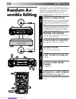
Connect your recorder’s AV1 IN/OUT connectors to the
VIDEO IN and AUDIO IN connectors on the recording
deck, and connect your recorder’s PAUSE/R.A. EDIT
connector to the PAUSE connector on the recording
deck.

If the recording deck doesn’t have a PAUSE connec-
tor, connect to the R.A. EDIT connector instead.

The Mini-plug cable is a mono 3.5 mm mini-plug to
mono 3.5 mm mini-plug connector.

PREPARE FOR EDITING

2

Insert the cassette to be recorded on into the recorder
and set the recorder's input mode.

LOAD SOURCE CASSETTE

3

Insert the source cassette into your recorder.

SET EDIT MODE

4

See "Editing Mode Setting" on page 32.

START SOURCE PLAYBACK

5

Press PLAY.

ACCESS MAIN MENU

SCREEN

6

Press MENU twice.

ACCESS R.A. EDIT SCREEN

7

Press PUSH JOG 

%fi

 to move the highlight bar

(pointer) to "R.A.EDIT", then press OK.

The screen is superimposed on the video playback in
step 8.

PAUSE/

R.A. EDIT

REMOTE

PAUSE

8

8

Player

Mini-plug Cable
(Not provided)

Another recorder

(w/PAUSE connector)

Audio signal

Video signal

Your recorder

Recorder

TIME SCAN SHUTTLE

STOP

PLAY

0

4

1

3

CANCEL

STOP

PLAY

PUSH JOG

OK

MENU

IN/OUT

START

JOG

Summary of Contents for HR-S9400EK

Page 1: ...YOUR NEW RECORDER 4 Basic Connections 4 S VIDEO Connection 6 INITIAL SETTINGS 8 Video Channel Set 8 Auto Set Up 10 Video Plus Setup 12 PLAYBACK 14 Basic Playback 14 Playback Features 15 TimeScan 20 RECORDING 22 Basic Recording 22 Recording Features 23 TIMER RECORDING 26 Video Plus Timer Recording 26 Regular Timer Programming 28 EDITING 32 Preparation For Editing 32 Edit To Or From Another Video Re...

Page 2: ...y caution are on the rear of the unit WARNING DANGEROUS VOLTAGE INSIDE WARNING TO PREVENT FIRE OR SHOCK HAZARD DO NOT EXPOSE THIS UNIT TO RAIN OR MOISTURE Safety Precautions Video tapes recorded with this video recorder in the LP Long Play mode cannot be played back on a single speed video recorder The STANDBY ON button does not completely shut off mains power from the unit but switches operating ...

Page 3: ...ecifically stated that it is de signed for unattended operation or has a standby mode Switch off using the switch on the equipment and make sure that your family knows how to do this Special arrangements may need to be made for infirm or handicapped people DON T use equipment such as personal stereos or radios so that you are distracted from the requirements of road safety It is illegal to watch t...

Page 4: ... Disconnect the TV aerial cable from the TV b Connect the TV aerial cable to the ANT IN jack on the rear panel of the recorder c Connect the provided RF cable between the RF OUT jack on the rear panel of the recorder and the TV s aerial connector Before operating the recorder make sure the TV s channel is set to the VIDEO channel Z pg 8 AV CONNECTION To Connect To A TV with 21 pin AV input connect...

Page 5: ...but can deliver either a composite video signal or a Y C signal a signal in which the luminance and chrominance signals are separated according to the setting of the rear panel AV1 OUT switch If your TV s 21 pin AV input connector SCART is compatible only with the regular video signal set this switch to COMP If your TV s 21 pin AV input connector SCART is compatible with the Y C signal set this sw...

Page 6: ... the TV s AUDIO IN connectors CONNECT RECORDER TO MAINS 2 Plug the end of the mains power cord into a mains outlet For TV sets with an S VIDEO input connector S VIDEO Connection IMPORTANT To operate the recorder with your TV using the S VIDEO connection set your TV to the VIDEO or AV mode Mains outlet Mains Power Cord NOTE If your television is not stereo capable use the recorder s AUDIO OUT conne...

Page 7: ...inished all the necessary connections go to Video Channel Set on page 8 then perform Auto Set Up on page 10 do NOT press the button on the recorder remote control to turn on the recorder s power before you start Auto Set Up Back of Recorder Aerial or Cable RF Cable provided ...

Page 8: ...o vertical white bars appear clearly on the screen as shown in the illustration at bottom left go to step 3 If the two vertical white bars do not appear clearly press TV PROG or to set the video recorder to a vacant channel between 22 and 69 which is not occupied by any local station in your area Refer to list on page 55 for details of broadcast stations in your area Then set your TV to UHF channe...

Page 9: ...T MODE 1 Press and hold down STOP on the recorder until the display panel shows the following SET VIDEO CHANNEL 2 Press TV PROG until the display panel shows OUT Now the video channel is set to off EXIT VIDEO CHANNEL SET MODE 3 Press OK TURN OFF THE RECORDER 4 Press To view picture signals from the video recorder set your TV to its AV mode After you finish this step go to Auto Set Up on page 10 4 ...

Page 10: ...er s memory and the recorder will not perform Auto Set Up again You only need to set the clock Z pg 56 If you have moved to a different area perform each setting as required Tuner setting Z pg 48 Clock setting Z pg 56 Video Plus Guide Program number setting Z pg 12 If a new station starts broadcasting in your area perform both tuner setting Z pg 48 and Video Plus Guide Program number setting Z pg ...

Page 11: ...such as to add or skip channels to change preset positions or to set or change station names see pages 50 53 2 Perform Video Plus Setup on page 12 to check if the Guide Program numbers have been set correctly b If auto channel set has succeeded but auto clock set has not 1 Turn on the TV and select its VIDEO channel or AV mode then make sure that all necessary stations have been stored in the reco...

Page 12: ...lowing procedure is not necessary NOTE Guide Program GUIDE PROG number refers to the assigned TV station numbers according to broadcast area for Video Plus timer recording IMPORTANT Perform the following procedure after Auto Set Up on page 10 and or the channel setting steps on pages 48 53 and after the Clock Set procedure on page 56 After setting the Guide Program numbers the station names and pr...

Page 13: ...and selection is complete If you already know the Guide Program number for a station 1 After step 3 press PUSH JOG The GUIDE PROG number starts to flash 2 Enter the Guide Program number using the NUMBER keys or PUSH JOG fi then press PUSH JOG The TV PROG number starts to flash 3 Enter the preset position using the NUMBER keys or PUSH JOG fi then press PUSH JOG Repeat 2 and 3 as necessary 4 Press M...

Page 14: ... To go forward press FF or turn the TIME SCAN SHUTTLE ring to the right START PLAYBACK 3 Press PLAY Playback picture quality of LP recordings will not be as high as SP recordings STOP PLAYBACK 4 Press STOP on the remote or STOP EJECT on the recorder s front panel Then press STOP EJECT to remove the cassette Turn on the TV and select the VIDEO channel or AV mode 8 1 2 4 5 3 6 8 0 7 9 2 4 1 3 P L A ...

Page 15: ...back to decrease speed in the forward direction To play in reverse slow motion and in reverse play mode continue to turn the TIME SCAN SHUTTLE ring to the left or press PUSH JOG after selecting all the forward direction slow motion modes OR During still picture turn the TIME SCAN SHUTTLE ring to the right for forward slow motion or to the left for reverse slow motion OR During still picture press ...

Page 16: ...n the remote to engage manual tracking ADJUST TRACKING MANUALLY 2 Press TV PROG or to adjust tracking RETURN TO AUTOMATIC TRACKING 3 Press on the remote to re engage automatic tracking NOTE When a new tape is inserted the recorder enters the automatic tracking mode automatically 3R Picture Your video recorder is equipped with the 3R Picture System During playback 3R Resolution and Response Recover...

Page 17: ... beginning of each recording This function gives you quick access to any one of 9 index codes in either direction NOTE Before starting make sure the recorder is in the Stop mode ACTIVATE INDEX SEARCH 1 Press PUSH JOG or or 1 or 1 is displayed on screen and search begins in the corresponding direction To access index codes 2 through 9 press PUSH JOG or repeatedly until the correct index number is d...

Page 18: ...eld when you play back any stereo source or view a stereo programme while recording it SpatializerW has no effect on recording quality ACTIVATE SPATIALIZERW 1 Press SPATIALIZER the current setting will be displayed on the screen for about 5 seconds Pressing SPATIALIZER while the screen shows the display changes the setting To view a stereo programme such as movies or music select SPATIALIZER to cr...

Page 19: ...er cannot be used when the recorder is in the Record mode Scene Finder 10 minutes on counter FF REW FF REW FF REW Search Search Search 5 seconds 10 minutes on counter 5 seconds 5 seconds Repeat Playback Your video recorder can automatically play back the whole tape 20 times repeatedly START PLAYBACK 1 Press PLAY ACTIVATE REPEAT PLAYBACK 2 Press PLAY and hold for over 5 seconds then release The Pla...

Page 20: ...dio information will not be played so that the audio can keep up with the video 8 1 2 4 5 3 6 8 0 7 9 2 4 1 3 P L A Y OK MENU TIME SCAN indicator TIME SCAN SHUTTLE PLAY PUSH JOG 1 2 3 4 5 Audio signal during TimeScan Sound of 1 3 and 5 is heard Sound of 2 and 4 is not heard Output audio signal is normal monaural sound Playback tape ACTIVATE VARIABLE SPEED SEARCH 1 During playback or still turn the...

Page 21: ...e recorder s TIME SCAN indicator lights during TimeScan The speed is shown during TimeScan in the upper right corner of the TV screen for approx 5 seconds The display may be distorted To resume normal playback press PLAY When using the recorder s TIME SCAN SHUTTLE ring the playback speed may not change in the correct step if it is turned too fast Picture and audio may become distorted when the rec...

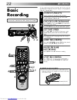
Page 22: ... on the recorder display panel to confirm the selected tape speed Picture quality of LP recordings will not be as high as SP recordings START RECORDING 4 Press and hold RECORD and press PLAY on the remote control or press RECORD on the recorder PAUSE RESUME RECORDING 5 Press PAUSE Press PLAY to resume recording STOP RECORDING 6 Press STOP on the remote control or STOP EJECT on the recorder Then pr...

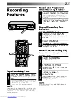
Page 23: ...ecording or playback The counter is reset to 0 00 00 and shows the exact elapsed time as the tape runs SELECT PRESET TO WATCH 1 Once recording is in progress all you need to do is to set the preset controls on the TV for the station you wish to view The programme selected with the TV s preset controls appears on the TV screen while the one selected with the recorder s TV PROG buttons is recorded o...

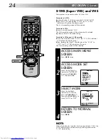
Page 24: ... to OFF the S S VHS indicator will go out The VHS recording mode will be selected ACCESS MAIN MENU SCREEN 1 Press MENU twice ACCESS MODE SET SCREEN 2 Move the highlight bar pointer to MODE SET by pressing PUSH JOG fi then press OK SELECT MODE 3 Move the highlight pointer to S VHS by pressing PUSH JOG fi then press PUSH JOG to select AUTO or OFF RETURN TO NORMAL SCREEN 4 Press MENU MAIN MENU MODE S...

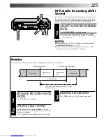
Page 25: ...ory results If necessary you can adjust the Hi Fi audio recording level more precisely by reffering to the audio level indicator on the front panel Retake You can cut out unnecessary parts of a TV programme while you re recording it End of programme Programme Beginning of programme Programme Recorded part RESUME RECORDING 3 Press PLAY when you wish to resume recording ENGAGE RECORD PAUSE MODE 1 Pr...

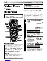
Page 26: ... Guide Program Numbers must be set properly be sure to read Video Plus Setup Z pg 12 before you start With Video Plus timer programming is greatly simplified because each TV programme has a corresponding code number which your recorder is able to recognise During Video Plus and regular timer programming the Illumi Guide feature tells you which button on the remote control must be pressed next by l...

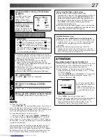
Page 27: ...s recorder to timer record as many as 8 programmes If you try to programme the recorder to record a ninth PROGRAM FULL appears on screen and FULL appears on the front display panel To record the extra programme you must first cancel any unnecessary programmes Z pg 30 When Using The Illumi Guide Feature Buttons light or blink on the remote control for approximately 10 seconds If the button or butto...

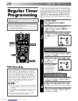
Page 28: ...imer record the programme Or you can use the Illumi Guide feature where the remote control tells you which button to press next by lighting it up To use the Illumi Guide feature with the TV SAT VCR switch set to VCR press ILLUMI GUIDE before performing step 1 PROG REW PLAY FF light up at this time If you aren t going to use the Illumi Guide feature go directly to step 1 4 5 6 8 0 7 9 4 1 3 START S...

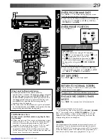
Page 29: ...ROG 25 12 1 BBC 1 MENU EXIT Satellite Receiver Users To timer record a satellite broadcast using Regular Timer Programming Before you start step 1 be sure to set the recorder s input mode to AUX2 Z pg 33 Do NOT change the input mode until the selected programme has been timer recorded In step 6 you have to select AUX2 as well Before the selected programme begins select the appropriate channel on t...

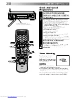
Page 30: ... deleted REVISE PROGRAMME INFORMATION 2 Input the appropriate data using the START STOP DATE and TV PROG buttons on the remote control TIMER RECORDING cont Timer Warning WARNING TIMER RECORDING TO START SOON CANCEL If you have programmed your recorder to timer record a programme or a series of programmes a warning appears on screen to tell you that the recording is to start in 5 minutes NOTES The ...

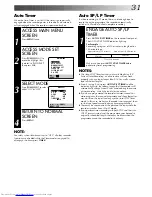
Page 31: ...make sure the mode is not engaged then set the tape speed manually during timer programming There may be some noise at the point on the tape where the recorder switches from SP to LP mode If you perform timer recording with both PDC and the Auto SP LP Timer activated and the programme goes beyond its originally scheduled length there may be times when the programme cannot be recorded in its entire...

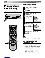
Page 32: ...IME SCAN ON AUDIO 5 ON OFF MENU EXIT NOTE After you finish editing be sure to set EDIT back to OFF Advantages Of S VHS Video Recorders EDITING You can edit from VHS to S VHS S VHS to VHS or from S VHS to S VHS From VHS to S VHS VIDEO VIDEO connection Record VHS playback signals in the S VHS mode Although the picture quality is inherently limited by that of the original the edited tape has better p...

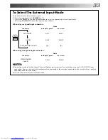
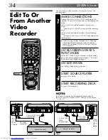
Page 33: ...nel input connectors Connector NOTES Connections made to the front panel Video and Audio inputs automatically override the rear panel AUDIO VIDEO input connection If you wish to edit with another machine connected to the rear input connector make sure that there is nothing connected to the front connectors Use the L connector for monaural connection When using rear panel input connectors AU 1 AU 2...

Page 34: ...ecorder s S IN S OUT and AUDIO IN OUT connectors SET RECORDING DECK S INPUT MODE 2 Set to AUX When using this recorder as the recording deck select the appropriate input mode Z To Select The External Input Mode on page 33 SET EDIT MODE 3 See Editing Mode Setting on page 32 START SOURCE PLAYER 4 Engage its Play mode START RECORDING DECK 5 Engage its Record mode NOTES All necessary cables can be obt...

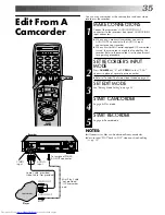
Page 35: ...corder s instruction manual for operating procedure SET RECORDER S INPUT MODE 2 Press NUMBER key 0 or TV PROG so that F AU appears in place of a preset position number Refer to To Select The External Input Mode on page 33 SET EDIT MODE 3 See Editing Mode Setting on page 32 START CAMCORDER 4 Engage its Play mode START RECORDER 5 Engage its Record mode NOTES All necessary cables can be obtained from...

Page 36: ...sn t have a PAUSE connec tor connect to the R A EDIT connector instead The Mini plug cable is a mono 3 5 mm mini plug to mono 3 5 mm mini plug connector PREPARE FOR EDITING 2 Insert the cassette to be recorded on into the recorder and set the recorder s input mode LOAD SOURCE CASSETTE 3 Insert the source cassette into your recorder SET EDIT MODE 4 See Editing Mode Setting on page 32 START SOURCE P...

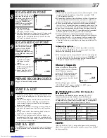
Page 37: ...have a counter reading that is at least 1 second after the corresponding edit in point Any less than 1 second and the edit out point will not be registered Since the source recorder prerolls during Random Assemble Editing there must be at least 15 seconds worth of recorded material prior to any edit in point on the source tape If the search time for an edit in point exceeds 5 minutes the recording...

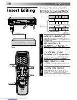
Page 38: ... The External Input Mode on page 33 LOCATE END POINT 3 Load the recording cassette into your recorder and play it back to determine the edit out point the end of the segment to be replaced using the JOG TIME SCAN SHUTTLE controls or PUSH JOG and PAUSE RESET THE COUNTER 4 Press C RESET to change the counter display to 0 00 00 LOCATE START POINT 5 Determine the edit in point the beginning of the seg...

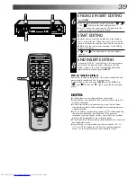
Page 39: ...e Hi Fi audio soundtrack and normal audio soundtrack all at the same time In step 6 above after you press INSERT press A DUB also and blink and lights up on the front display panel 1 2 4 5 3 6 8 0 7 9 2 4 1 3 8 NOTES Suitable leads can be obtained from your dealer Insert editing is not possible with cassettes whose safety tab has been removed When insert editing is performed on a tape that has bee...

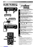
Page 40: ...ng press AUDIO MONITOR to select L R at this point Audio dubbing with audio mixing is not possible if you re using a monaural audio component or if you don t have an audio mixer START DUBBING 5 Engage the audio component s Play mode then press PLAY to start the tape in your recorder Audio dubbing begins at this point blinks and is displayed on the front display panel To stop dubbing temporarily pr...

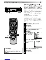
Page 41: ...ected to another device via its J terminal The ID Number is preset to 1 at the factory You can change this number to any number between 1 and 99 If it is necessary to change the JLIP ID number perform the following steps 1 2 4 5 3 6 8 0 7 9 2 4 1 3 8 OK MENU PUSH JOG ATTENTION After you change your recorder s JLIP ID number control signal transmission may not work properly If this happens turn off...

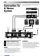
Page 42: ...m Some speakers and televisions are specially shielded to prevent television interference If both are of the non shielded type do not place the speakers adjacent to the TV set as this can adversely affect the video playback picture NOTES When connecting your recorder s audio output connectors to a stereo amplifier make sure you connect L and R correctly If NICAM TV broadcasts are receivable in you...

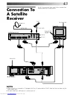
Page 43: ...connection to a satellite receiver NOTES When connecting your recorder to a TV equipped with 21 pin AV input connectors SCART follow the illustration above using the cables shown in gray For details check your satellite receiver s instruction manual Mains outlet TV Aerial cable Aerial connector Satellite Receiver Unit Satellite Cable Outdoor Unit Aerial Back of TV 21 pin AV input connectors SCART ...

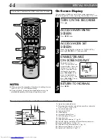
Page 44: ...y NOTES When you use this recorder as the player for editing be sure to set O S D to OFF before starting During playback the operation mode indicators may be disturbed depending on the type of tape being used You can choose whether or not to have various operational indicators appear on screen by setting this function ON or OFF TURN ON THE RECORDER 1 Press ACCESS MAIN MENU SCREEN 2 Press MENU twic...

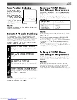
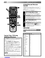
Page 45: ...POWER SUPPLY 1 Unplug the mains power cord from the mains outlet SET A B CODE SWITCH 2 Set to B RE SUPPLY POWER 3 Plug the mains power cord back into the mains outlet TURN THE RECORDER ON 4 Press on the remote control The recorder will now only respond to B code signals NOTE Some TV sets may malfunction in response to the B mode If this happens switch back to the A mode To Record NICAM Stereo And ...

Page 46: ...ng the NUMBER keys then press STOP JVC has four codes If the TV does not function with one code try entering another You don t have to repeat this step until you replace your remote control s batteries TRY OPERATING TV 2 Press on the remote to turn the TV off If it goes off try other operations The button TV VCR button TV PROG button TV VOL fi button and Mute button on the remote can all be used t...

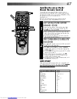
Page 47: ... replace your remote control s batteries TRY OPERATING SATELLITE RECEIVER 2 Press on the remote to turn the satellite receiver off If it goes off try other operations The button TV PROG button NUMBER buttons on the remote can all be used to operate the satellite receiver The NUMBER buttons will not work with JVC satellite receivers using code 13 With satellite receivers using Code 16 the button co...

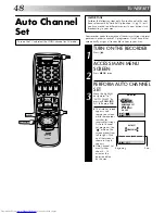
Page 48: ...receivable stations in your area TURN ON THE RECORDER 1 Press ACCESS MAIN MENU SCREEN 2 Press MENU twice PERFORM AUTO CHANNEL SET 3 Move the highlight bar pointer to AUTO CH SET by pressing PUSH JOG fi then press OK The Auto Set screen appears and remains on screen while the recorder searches for receivable stations As Auto Channel Set progresses the mark on the screen moves from left to right Wai...

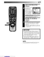
Page 49: ...tored in order and the station names may not be stored correctly 5 5 PR CH ID PR CH ID 01 26 BBC1 08 02 33 BBC2 09 03 23 ITV 10 04 30 CH4 11 05 37 CH5 12 06 13 07 14 5 EDIT CANCEL DELETE MENU EXIT 5 5 IMPORTANT Depending on the reception conditions the station names may not be stored correctly and auto Guide Program Number Set may not work properly If the Guide Program numbers are not set properly...

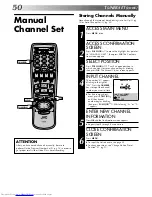
Page 50: ...ight of CH Press the NUMBER keys to input the channel number you want to store For fine tuning adjust ment press PUSH JOG until the channel number begins blinking then press PUSH JOG fi While tuning F or F appears ENTER NEW CHANNEL INFORMATION 5 Press OK and the Confirmation screen appears Repeat steps 3 through 5 as necessary CLOSE CONFIRMATION SCREEN 6 Press MENU To input the station name see pa...

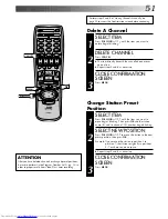
Page 51: ...le If you moved the station in position 3 to position 7 the stations originally in positions 4 7 each move up one space Repeat steps 1 and 2 as necessary CLOSE CONFIRMATION SCREEN 3 Press MENU SELECT ITEM 1 Press PUSH JOG fi until the item you want to delete begins blinking DELETE CHANNEL 2 Press CANCEL The item directly beneath the cancelled one moves up one line Repeat steps 1 and 2 as necessary...

Page 52: ...sary CLOSE CONFIRMATION SCREEN 4 Press MENU Set Stations A OK MENU TUNER SET cont NOTE First perform step 1 of the above procedure SELECT STATION NAME CHARACTER 2 Press PUSH JOG and the first letter of the station name begins blinking ENTER NEW CHARACTER 3 Press PUSH JOG fi to cycle through the characters A Z 0 9 space and stop when the desired one is indicated then press PUSH JOG to enter Enter t...

Page 53: ...1 Press PUSH JOG fi until the channel you want to tune begins blinking ACCESS MANUAL CH SET SCREEN 2 Press OK three times The Manual Ch Set screen appears PERFORM TUNING 3 Press PUSH JOG fi until the picture is its clearest Then press OK The Confirmation screen appears Repeat steps 1 through 3 as necessary CLOSE CONFIRMATION SCREEN 4 Press MENU Fine Tuning Channels Already Stored MENU ...

Page 54: ...RAI2 RAI2 RAI3 RAI3 RB1 RB1 RB3 RB3 Rikisutvarpid S RKPS RTBF 1 RTB1 RTBF 2 RTB2 RTE 1 RTE1 RTL RTL RTL 2 RTL2 RTP RTP STATION NAME ID SAT SAT 1 SAT1 Scottish TV SCOT SC4 SC4 SDR SDR SDR1 SDR1 SFB1 SFB1 SFB3 SFB3 SKY Sky One SKY1 Sky Net SKYN Sport SPRT SR 1 SR1 Super RTL SRTL STV Test STVT STV 1 STV1 STV 2 STV2 Suedwest3 SW3 SWF 1 SWF1 Schweiz4 SWZ4 TYNE TEES TEES Text TEXT TF1 TF1 TNT int TNT TR...

Page 55: ...lneston 62 55 59 65 Midlands Ridge Hill 22 28 25 32 Sutton Coldfield 46 40 43 50 The Wrekin 26 33 23 29 Waltham 58 64 61 54 North Belmont 22 28 25 32 Emley Moor 44 51 47 41 BBC1 BBC2 ITV CH4 North West Caldbeck 30 34 28 32 Winter Hill 55 62 59 65 North East Bilsdale West Moor 33 26 29 23 Chatton 39 45 49 42 Pontop Pike 58 64 61 54 Scotland Angus 57 63 60 53 Black Hill 40 46 43 50 Sandale 22 Caldbe...

Page 56: ...adjustments at regular intervals by reading data from a PDC signal The Just Clock option appears in the Clock Set and Auto Clock Set screens and can be set ON or OFF the default setting is ON Press OK until the Just Clock setting begins blinking then press PUSH JOG fi to change the setting IMPORTANT If you turn off Just Clock off the accuracy of your recorder s built in clock may be reduced which ...

Page 57: ...s OK The minutes display begins blinking Repeat the procedure to set the minutes day month and year SET JUST CLOCK 5 The default setting is ON Set as desired by pressing PUSH JOG fi then press OK If you set to OFF you can disregard the next step as you won t be able to receive regular clock adjust ments SET CLOCK DATA SOURCE PRESET 6 The recorder is preset to receive clock setting and adjustment d...

Page 58: ...rder s VIDEO channel has not been correctly set If you re using the AV or S VIDEO connection the TV receiver is not set to the AV mode The automatic tracking mode is engaged The automatic tracking mode is engaged Automatic tracking is engaged The video heads may be dirty CORRECTIVE ACTION If you are using the RF OUT connec tion set the TV receiver to the VIDEO channel Z pg 8 Perform Video Channel ...

Page 59: ...ding is in progress The timer is engaged but there s no cassette loaded The loaded cassette has had its Record Safety tab removed TIMER has been pressed when there are no programs in memory or the timer record information has been programmed incorrectly The end of the tape was reached during timer recording The recorder s preset positions have been set incorrectly CORRECTIVE ACTION Position the ca...

Page 60: ...h the recorder off and unplug the mains power cord Then plug it in again and turn the recorder on Take out the cassette After checking the cassette operate the unit as usual RECORDING Q When I pause and then resume a recording the end of the recording before the pause is overlapped by the beginning of the continuation of recording Why does this happen A This is normal It reduces distortion at the ...

Page 61: ... 250 lines VHS 400 lines S VHS Frequency range 70 Hz to 10 000 Hz Normal audio 20 Hz to 20 000 Hz Hi Fi audio Input Output 21 pin scart connectors IN OUT x 1 IN x 1 RCA connectors VIDEO IN x 1 AUDIO IN x 2 AUDIO OUT x 1 S Video connectors IN x 1 OUT x 1 SPECIFICATIONS TUNER TIMER TV channel storage capacity 99 positions AUX position AU Tuning system Frequency synthesized tuner Channel coverage UHF...

Page 62: ...R Button engages timer standby mode Z pg 27 29 3 IN OUT Button registers edit in and edit out points in memory during R A Edit mode Z pg 37 4 SPATIALIZER Button enables disables SpatializerT Z pg 18 5 START Button starts automatic editing Z pg 37 6 A DUB Button engages Audio Dubbing mode Z pg 40 7 INSERT Button engages Insert Editing mode Z pg 39 8 Cassette Loading Slot is where cassette is insert...

Page 63: ...iting Z pg 35 AV S SELECT Button selects recorder s external input mode Z pg 33 q J Terminal JLIP Joint Level Interface Protocol Connector enables connection of a personal computer or similar device to allow computer ized control of the recorder during editing and certain other operations Z pg 41 w AUTO SP LP TIMER Button engages Auto SP LP Timer for automatic switching from SP to LP mode during t...

Page 64: ...r enables connection of aerial Z pg 4 7 AUDIO IN L R Connectors enable connection of audio cassette recorder camcorder or second video recorder input recordable when S selected Z pg 42 8 AUDIO OUT L R Connectors enable connection of audio cassette recorder TV or second video recorder for dubbing Z pg 42 9 AV2 IN Connector enables connection of second recorder or satellite receiver input recordable...

Page 65: ...ecording and shows how many programmes have been timer recorded Z pg 17 9 Audio Mode Indicator displays audio output mode currently selected Z pg 18 0 Cassette Loaded Mark lights once a cassette is inserted remains lit until cassette ejected or power turned off Tape Speed Indicators display mode of record ing light during Record or Play mode Z pg 22 Tape Remaining Time Indicator displays time rema...

Page 66: ...Auto Tracking Button enables disables auto tracking mode during playback Z pg 16 Digit Entry Button is used in controlling connected TV Z pg 46 0 AUDIO MONITOR Button changes output sound mode Z pg 18 TV Mute Button mutes sound of con nected TV Z pg 46 Rewind REW Button rewinds the tape Z pg 14 initiates high speed reverse search Z pg 15 Play Button same as button on recorder Z pg 14 Record Button...

Page 67: ...der Z pg 15 p Stop Button same as button on recorder Z pg 14 Q PROG CHECK Button accesses Program screens displays to check the program that you have programmed next program s information screen display appears each time button is pressed Z pg 30 W OK Button enters selections made in on screen menus Z pg 12 E TV VOL fi Button controls volume of connected TV Z pg 46 R ILLUMI GUIDE Button engages Il...

Page 68: ...VICTOR COMPANY OF JAPAN LIMITED ...

Reviews: