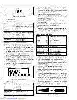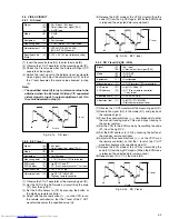
2-7
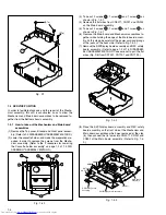
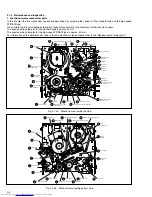
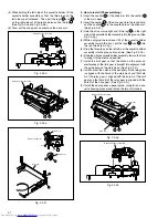
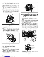
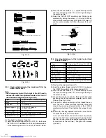
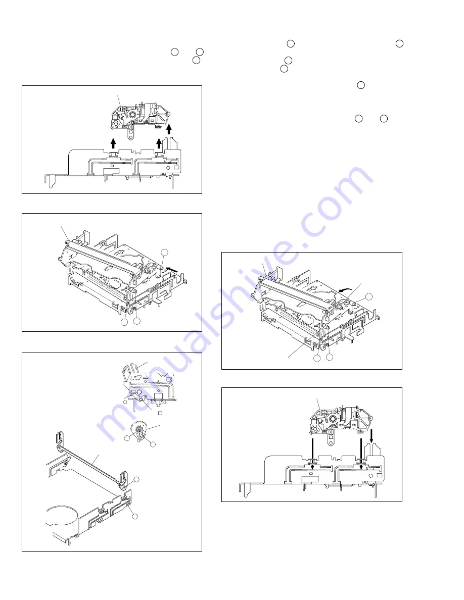
Fig. 2-2-3d
(5) While holding the left side of the cassette holder, lift the
cassette holder assembly so that the three legs on the
left side are all released. Then pull the legs A and B
on the right side out of the rail and also pull up the leg C .
(See Fig.2-2-3d and Fig.2-2-3e.)
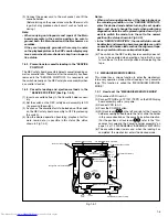
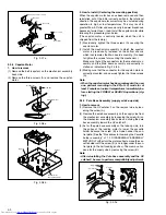
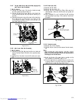
(6) Draw out the drive gear, and remove the drive arm.
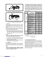
Fig. 2-2-3e
Cassette holder assembly
A
B
C
Cassette holder assembly
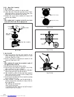
Fig. 2-2-3f
A
B
1
2
Hole
Hole
Drive arm
Drive gear
Drive arm
Main deck right side
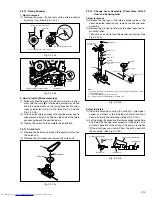
Fig. 2-2-3g
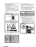
2. How to install (Phase matching)
(1) Insert the section A of the drive arm into the section B
of the main deck.
(2) Insert the section 1 of the drive gear into the round hole,
and the section 2 into the square hole on the drive arm.
(See Fig.2-2-3f.)
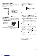
(3) Hold the drive arm upright and fit the leg C on the right
side of the cassette holder assembly into the groove. (See
Fig.2-2-3g.)
(4) While swinging the lock lever (R) of the cassette holder
assembly toward the front, put the legs A and B into
the rail. (See Fig.2-2-3g.)
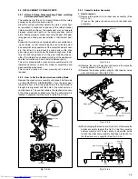
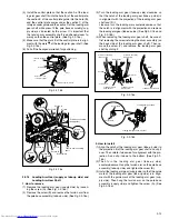
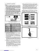
(5) Drop the three legs on the left side of the cassette holder
assembly into the groove at one time. (See Fig.2-2-3h.)
(6) Slide the whole cassette holder assembly toward the front
to bring it to the eject end position.
(7) Install the limit gear so that the notch on the outer cir-
cumference of the limit gear is brought into alignment with
the guide hole on the main deck. (See Fig.2-2-3i.)
(8) Install so that the notch on the periphery of the relay gear
is aligned with the notch of the main deck and that hole
A of the relay gear is aligned with the hole A of the limit
gear and that hole B of the relay gear is aligned with the
hole B of the drive gear. (See Fig.2-2-3i.)
(9) Install the door opener, opener guide, spring(A) and cas-
sette housing bracket and fasten the two slit washers.
A
B
C
Cassette holder assembly
Drive arm
Lock lever (R)
Fig. 2-2-3h
Cassette holder assembly

