1-3
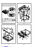
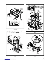
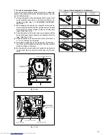
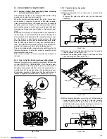
Fig. D3-2
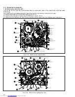
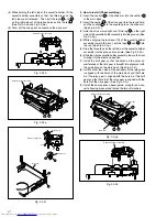
Fig. D4
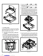
Fig. D5
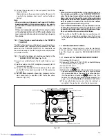
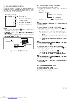
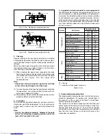
Fig. D6
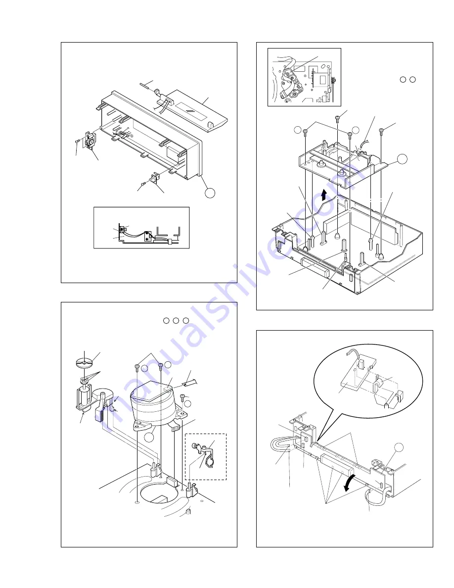
WIRING AND CONNECTION
OF THE EARTH WIRE <Note3c>
(S3c)
3
(S3a)
Holder
Earth
plate
WR3b
WR3c
Shaft
Membrane
door
assembly
(S3b)
Damper
assembly
(S5b)
(S5c)
(S5a)
<Note 5a>
5
(L5)
Spacer
<Note 5a>
(L5)
Spacer
<Note 5a>
Q3003
End sensor
<Note 5a>
Q3002
Start sensor
<Note 5a>
D3001
LED
<Note 5a>
WR5
Foil side
<Note 3a>
<Note 5b>
A/C head base
WR5
CN1
S3002
S cassette switch
<Note 5a>
a
b
Note:
When installing the Mechanism
assembly, secure the screws
(S5a) in the order of a , b .
(S4)
4
CN1
CN3501
a
c
CON1
b
WR4a
Foil side
<Note 3a>
(S4)
(L4a)
(L4b)
(P4)
Roller arm
assy
Inertia plate
(L4c)
WR4b
Foil side
<Note 3a>
Cleaner assy
Not use
Note:
When installing the Drum assembly, secure the
screws (S4) in the order of a , b , c .
(L6c)
CN7191
WR6c
Foil side
<Note 3a>
WR6b
Foil side
<Note 3a>
CN7001
WR6a
Supporting
tape side
<Note 3a>
(L6b)
(L6a)
REC safety
board assembly
<Note 6>
6
CN7192


