1-4
1.4 SERVICE POSITION
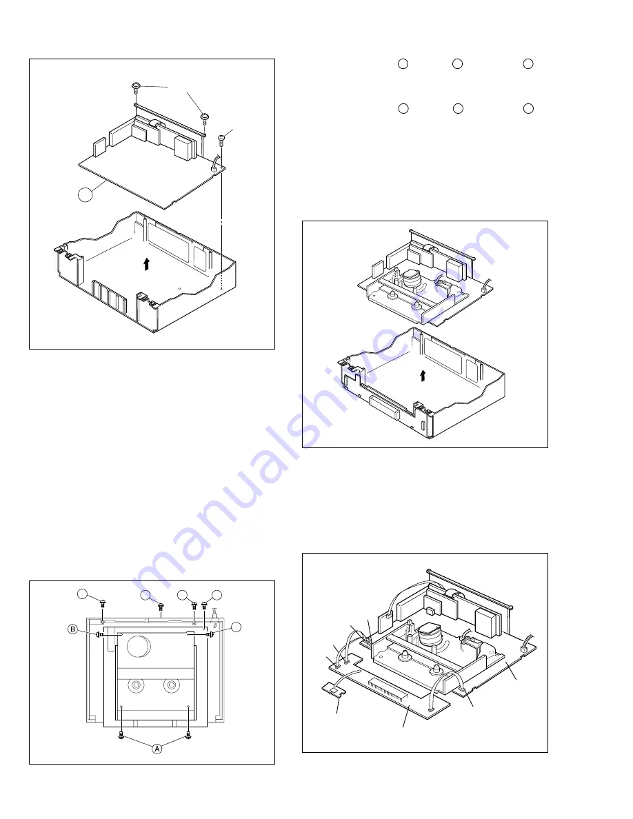
In order to facilitate diagnosis and the repair of the Mecha-
nism assembly, this unit is constructed so as to allow the
Mechanism and Main board assemblies to be removed to-
gether from the Bottom chassis assembly.
1.4.1
How to take out the Mechanism and Main board
assemblies
(1) Remove the Top cover, Bracket and Front panel assem-
bly. (Refer to 1.3 DISASSEMBLY/ASSEMBLY METHOD.)
(2) Lower the cassette holder, and make the preparations re-
quired in order to remove the screws from the Mecha-
nism assembly. (Refer to the “Procedures for Lowering
the Cassette holder assembly” on page 1-2 of 1.3 DIS-
ASSEMBLY/ASSEMBLY METHOD.)
F
D
D
E
C
Fig. 1-4-1
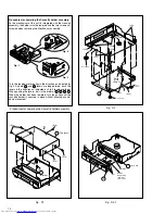
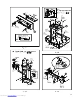
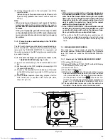
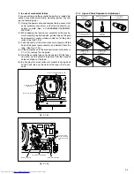
(3) Take out 2 screws A , 1 screw B and 1 screw C as
shown in Fig. 1-4-1.
(4) Remove the flat wires from CN3011, CN901 and CN902
on the Main board assembly.
(5) Take out 2 screws D , 1 screw E and 1 screw F as
shown in Fig. 1-4-1.
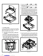
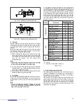
(6) Remove the Main board and Mechanism assemblies to-
gether while holding the edge of the Main board assem-
bly. At this stage be careful of the power cord and prongs
of the jacks on the back side. (Refer to Fig. 1-4-2.)
(7) Remove the SW/Display board assembly and REC safety
board assembly. (Refer to page 1-3 of 1.3 DISASSEM-
BLY/ASSEMBLY METHOD. Take care not to pull the flat
wires (Fig. D6) from CN7001, CN7191 and CN7192.)
Fig. 1-4-2
CN7192
CN3011
REC safety board
assembly
SW/Display board assembly
Main board
assembly
CN902
CN901
CN7191
Fig. 1-4-3
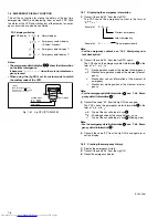
(8) Place the SW/Display board assembly and REC safety
board assembly on the front side of the Mechanism and
Main board assemblies which was removed at the step
(6), then connect the flat wires into CN3011, CN901 and
CN902 of the Main board assembly. (Refer to Fig. 1-4-
3.)
Fig. D7
7
(S7a)
(S7b)


