background image

EN


3

IMPORTANT PRODUCT
SAFETY INSTRUCTIONS

Electrical energy can perform many useful functions. But
improper use can result in potential electrical shock or fire
hazards. This product has been engineered and manufactured
to assure your personal safety. In order not to defeat the built-in
safeguards, observe the following basic rules for its installation,
use and servicing.

ATTENTION:

Follow and obey all warnings and instructions marked on your
product and its operating instructions. For your safety, please
read all the safety and operating instructions before you operate
this product and keep this booklet for future reference.

INSTALLATION

1. Grounding or Polarization

(A) Your product may be equipped with a polarized alternating-

current line plug (a plug having one blade wider than the
other). This plug will fit into the power outlet only one way.
This is a safety feature.
If you are unable to insert the plug fully into the outlet, try
reversing the plug. If the plug should still fail to fit, contact
your electrician to replace your obsolete outlet. Do not
defeat the safety purpose of the polarized plug.

(B) Your product may be equipped with a 3-wire grounding-type

plug, a plug having a third (grounding) pin. This plug will
only fit into a grounding-type power outlet. This is a safety
feature.
If you are unable to insert the plug into the outlet, contact
your electrician to replace your obsolete outlet. Do not
defeat the safety purpose of the grounding-type plug.

2. Power Sources

Operate your product only from the type of power source
indicated on the marking label. If you are not sure of the type of
power supply to your home, consult your product dealer or
local power company. If your product is intended to operate
from battery power, or other sources, refer to the operating
instructions.

3. Overloading

Do not overload wall outlets, extension cords, or integral
convenience receptacles as this can result in a risk of fire or
electric shock.

4. Power Cord Protection

Power supply cords should be routed so that they are not likely
to be walked on or pinched by items placed upon or against
them, paying particular attention to cords at plugs, convenience
receptacles, and the point where they exit from the product.

5. Ventilation

Slots and openings in the cabinet are provided for ventilation.
To ensure reliable operation of the product and to protect it
from overheating, these openings must not be blocked or
covered.
• Do not block the openings by placing the product on a bed,

sofa, rug or other similar surface.

• Do not place the product in a built-in installation such as a

bookcase or rack unless proper ventilation is provided or the
manufacturer’s instructions have been adhered to.

6. Wall or Ceiling Mounting

The product should be mounted to a wall or ceiling only as
recommended by the manufacturer.

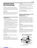
ANTENNA
LEAD IN WIRE

ANTENNA
DISCHARGE UNIT
(NEC SECTION 
810-20)

GROUNDING 
CONDUCTORS
(NEC SECTION 810-21)

GROUND CLAMPS

POWER SERVICE GROUNDING ELECTRODE SYSTEM
(NEC ART 250. PART H)

NEC – NATIONAL ELECTRICAL CODE

ELECTRIC SERVICE
EQUIPMENT

EXAMPLE OF ANTENNA GROUNDING AS PER

NATIONAL ELECTRICAL CODE, ANSI/NFPA 70

GROUND CLAMP

ANTENNA INSTALLATION

INSTRUCTIONS

1. Outdoor Antenna Grounding

If an outside antenna or cable system is connected to the
product, be sure the antenna or cable system is grounded so as
to provide some protection against voltage surges and built-up
static charges. Article 810 of the National Electrical Code,
ANSI/NFPA 70, provides information with regard to proper
grounding of the mast and supporting structure, grounding of
the lead-in wire to an antenna discharge unit, size of grounding
connectors, location of antenna discharge unit, connection to
grounding electrodes, and requirements for the grounding
electrode.

2. Lightning

For added protection for this product during a lightning storm,
or when it is left unattended and unused for long periods of
time, unplug it from the wall outlet and disconnect the antenna
or cable system. This will prevent damage to the product due to
lightning and power-line surges.

3. Power Lines

An outside antenna system should not be located in the vicinity
of overhead power lines or other electric light or power circuits,
or where it can fall into such power lines or circuits. When
installing an outside antenna system, extreme care should be
taken to keep from touching such power lines or circuits as
contact with them might be fatal.

Summary of Contents for HR-VP48U

Page 1: ...O SP EP MENU CH OK POWER REC PAUSE STOP EJECT PLAY FF REW SP EP VCR TV CH L O V V T H C V T L O V V T CANCEL TIMER START STOP DATE PLAY REW REC STOP SHUTTLE PLUS PAUSE FF MENU OK CH TV VCR C RESET DAILY M F AUX WEEKLY PROG CHECK PROG SP EP SKIP SEARCH DISPLAY A MONITOR 1 7 8 9 2 4 1 3 EXPRESS PROGRAMMING VCR TV LP20878 001 ENTER OSD 2 3 4 5 6 0 TV operation n Press and hold TV button then press PO...

Page 2: ...rounding system of the building as close to the point of cable entry as practical CAUTION Changes or modifications not approved by JVC could void user s authority to operate the equipment 䡲 Cassettes marked VHS or S VHS can be used with this video cassette recorder However S VHS recording is not possible with this model 䡲 This model is equipped with SQPB S VHS QUASI PLAYBACK that makes it possible...

Page 3: ... paying particular attention to cords at plugs convenience receptacles and the point where they exit from the product 5 Ventilation Slots and openings in the cabinet are provided for ventilation To ensure reliable operation of the product and to protect it from overheating these openings must not be blocked or covered Do not block the openings by placing the product on a bed sofa rug or other simi...

Page 4: ...ctions on the front and rear panel the front display panel and the Remote The 墌 mark signals a reference to another page for instructions or related information Operation buttons necessary for the various procedures are clearly indicated through the use of illustrations at the beginning of each major section BEFORE YOU INSTALL YOUR NEW VCR please read the sections literature listed below CAUTIONS ...

Page 5: ... Tuner Setting 13 Setting channels automatically Auto Channel Set 13 Setting channels manually Manual Channel Set 14 BASIC PLAYBACK AND RECORDING 15 Basic Playback 15 Basic Playback Features 16 Changing display information 16 Checking tape position 16 Playing back tape repeatedly Repeat Play 16 Adjusting tracking condition Tracking Adjustments 17 Automatic operations after rewinding Next Function ...

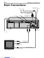
Page 6: ...le supplied Matching transformer not supplied AC Power Cord Audio video cable not supplied TV ANTENNA IN Antenna or cable input Back of VCR To 75 ohm terminal AC Outlet Antenna or cable Flat feeder Coaxial cable Basic Connections AUDIO OUT VIDEO OUT To Audio video input connectors ...

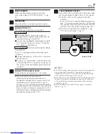
Page 7: ...outlet 墌 pg 8 If Auto or CH is displayed on the front display panel before the VCR is turned on the clock and tuner channels are being set automatically Wait until the clock time is displayed on the front display panel before turning on the VCR 5 Final preparation for use Turn on the VCR and set the CH3 CH4 switch on the rear shown below to either CH3 or CH4 correctly The CH3 CH4 switch is preset ...

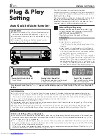
Page 8: ...l Set or Manual Channel Set 墌 pg 13 or 14 INITIAL SETTINGS Plug Play Setting This VCR sets the clock and tuner channels automatically when AC power cord is first connected to an AC outlet The antenna cable must be connected for the Plug Play setting The time and date can be set automatically by the clock setting data transmitted from one of the regular TV broadcast channels We call this TV channel...

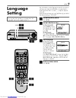
Page 9: ...IAL SET then press OK or SHUTTLE PLUS 3 3 Select language On the front panel Press CH5 to move the highlight bar arrow to LANGUAGE then press OK repeatedly until the desired language is selected On the Remote Press SHUTTLE PLUS 5 to move the highlight bar arrow to LANGUAGE then press OK or SHUTTLE PLUS 3 repeatedly until the desired language is selected 4 Return to normal screen Press MENU Turn on...

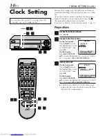
Page 10: ...Press SHUTTLE PLUS 5 to move the highlight bar arrow to INITIAL SET then press OK or SHUTTLE PLUS 3 3 Select clock set On the front panel Press CH5 to move the highlight bar arrow to CLOCK SET then press OK On the Remote Press SHUTTLE PLUS 5 to move the highlight bar arrow to CLOCK SET then press OK or SHUTTLE PLUS 3 CABLE BOX USERS SET CLOCK MANUALLY appears on the screen for about 5 seconds then...

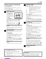
Page 11: ...T AUTO TIME ZONE AUTO PRESS 5 THEN OK PRESS MENU TO END 6 Select D S T mode You have three choices AUTO Select if you want to adjust your VCR s clock automatically by the incoming signal from the host channel Auto Daylight Saving Time ON Adjustment will be made by the clock itself OFF Select when Daylight Saving Time does not apply to you On the front panel Press CH5 to move the highlight bar to D...

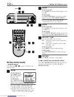
Page 12: ...the Remote Press SHUTTLE PLUS 5 to select the desired setting 8 Start clock Press MENU and normal screen appears To make corrections any time during the process Press OK or SHUTTLE PLUS 3 repeatedly until the item you want to change blinks then press CH 5 or SHUTTLE PLUS 5 CLOCK SET TIME DATE YEAR AM 1 1 00 AUTO CLOCK ON HOST CH AUTO CATV D S T AUTO TIME ZONE AUTO PRESS 5 THEN OK PRESS MENU TO END...

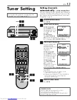
Page 13: ... AUTO CHANNEL SET then press OK On the Remote Press SHUTTLE PLUS 5 to move the highlight bar arrow to AUTO CHANNEL SET then press OK or SHUTTLE PLUS 3 NOTES When Auto Channel Set is complete SCAN COMPLETED appears on screen If the scan was unsuccessful SCAN COMPLETED NO SIGNAL appears on screen Check the connections and start again 4 Return to normal screen Press MENU INFORMATION The VCR selects t...

Page 14: ...SHUTTLE PLUS 3 to set to ADD 3 Repeat 1 and 2 to add other channels To skip channels On the front panel 1 Press CH5 to select a channel number you want to skip 2 Press OK to set to SKIP 3 Repeat 1 and 2 to skip other channels On the Remote 1 Press the Number keys or SHUTTLE PLUS 5 to input a channel number you want to skip 2 Press OK or SHUTTLE PLUS 3 to set to SKIP 3 Repeat 1 and 2 to skip other ...

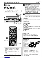
Page 15: ... VCR and the TV and select the VCR channel 3 or 4 or AV mode on the TV Usable cassettes Full Size VHS T 30 ST 30 T 60 ST 60 T 90 T 120 ST 120 T 160 ST 160 ST 210 Compact VHS TC 20 ST C20 TC 30 ST C30 TC 40 ST C40 Compact VHS camcorder recordings can be played on this VCR Simply place the recorded cassette into a VHS Cassette Adapter and it can be used just like any full sized VHS cassette This VCR...

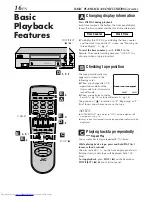
Page 16: ...en you perform an Index Search 墌 pg 18 or Instant Review 墌 pg 18 The position of in relation to B Beginning or E End shows you where you are on the tape NOTES SUPERIMPOSE must be set to ON or the indicator will not appear 墌 pg 33 It may take a few seconds for the tape position indicator to be displayed Playing back tape repeatedly Repeat Play You can play back a tape repeatedly 100 times While pla...

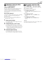
Page 17: ...reen Press CH 5 and or CH and on the Remote Press it briefly for a fine adjustment or press and hold for coarse adjustment Watch the screen and continue adjustment until optimum picture and sound quality are achieved 3 Reactivate automatic tracking Press CH 5 and on the front panel at the same time The automatic tracking becomes active again Automatic operations after rewinding Next Function Memor...

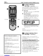
Page 18: ...tomatically You can access a program of 2 to 9 index codes away from the current position on the tape If for example you have 5 programs recorded and you want to watch the third one press REVIEW three times Ifyouwanttofindtheverybeginningofthedesiredprogram press REW 1 or FF after playback starts If the tape is already rewound when REVIEW is pressed it will play the tape from the beginning It will...

Page 19: ...C On the Remote While holding REC press PLAY 3 To pause recording Press PAUSE 8 To resume recording press PLAY 3 To stop recording Press STOP 7 on the Remote or STOP EJECT 7 0 on the front panel To rewind the tape Press REW 1 To fast forward the tape Press FF To eject the tape Press STOP EJECT 7 0 on the front panel when the tape is not running You can also eject the cassette with the VCR turned o...

Page 20: ...anel repeatedly until the recording length you want appears on the front display panel The record indicator starts flashing Each time you press the button recording length increases in 30 minute intervals up to 6 hours To cancel an ITR press STOP 7 on the Remote or STOP EJECT 7 0 on the front panel Watching one program while recording another 1 Engage TV mode During recording If you connect the TV...

Page 21: ...or 5 seconds The time counter remains on the screen indicating the elapsed time The indications are not recorded 2 Erase on screen display Press OSD again NOTE If the VCR is in recording pause mode RECORD PAUSE is always displayed The VCR status can be also displayed during playback Other useful function for recording You can also use the following function for recording Recording Resume Function ...

Page 22: ... resumes To resume normal playback press PLAY 3 7 Variable Speed Picture Search You can change the speed of picture search How to use the SHUTTLE PLUS buttons on the Remote To do forward picture search press SHUTTLE PLUS repeatedly Each time you press the button the search speed increases To decrease the speed while forward picture search toward normal playback then reverse picture search press SH...

Page 23: ...d on the front panel or CH or on the Remote to adjust tracking E D Viewing still picture Still Picture Playback Press PAUSE 8 during normal playback Playback is freezed and a still picture appears To resume normal playback press PLAY 3 NOTE To obtain a noiseless still picture it may be necessary to adjust tracking in slow motion playback before starting still picture playback Skipping unwanted por...

Page 24: ...f not cover the hole with adhesive tape then load it into the VCR The VCR turns on and the counter is reset automatically 2 Access VCR Plus screen Press PROG on the Remote The clock must be set to access the VCR Plus screen If you have not set the clock the Main Menu screen appears after an error message is displayed Refer to page 8 for the Plug Play setting or page 10 for the clock setting proced...

Page 25: ...s set the correct guide channel number for that station 墌 pg 26 VCR Plus Setup NOTES Even if a power failure occurs the VCR keeps your timer programs However the clock time channel settings and other menu settings are lost if it lasts for more than 3 minutes As a result when the power is supplied again to this VCR after the power failure the following will take place 1 This VCR starts the Plug Pla...

Page 26: ...s programing system assigns a VCR Plus guide channel to the TV channels and the cable channels These guide channel numbers are also called the VCR Plus channel codes Most TV listings have a section usually a chart indicating the guide channel numbers assigned to each station For accurate VCR Plus programing the VCR Plus guide channel number for each station should match the channel number on which...

Page 27: ...US 3 Ex When inputting the guide channel number 6 for WNJU Ind Ex If WNJU Ind is received on channel 47 GUIDE CHANNEL SET GUIDE CH 6 VCR CH PRESS NUMBER KEY 0 9 OR 5 THEN OK PRESS MENU TO END INITIAL SET CLOCK SET LANGUAGE ENGLISH GUIDE CHANNEL SET SELECT WITH 5 AND OK PRESS MENU TO END GUIDE CHANNEL SET GUIDE CH 6 VCR CH 47 PRESS NUMBER KEY 0 9 OR 5 THEN OK PRESS MENU TO END MAIN MENU FUNCTION SE...

Page 28: ... 5 Set program stop time Press STOP repeatedly to enter the time you want recording to stop Press and hold STOP to increase the time in 30 minute intervals 6 Set program date Press DATE The current date is displayed on the screen The date you enter appears in its place 7 Set channel number Press CH Holding down CH rapidly changes the channel numbers If you receive your programs through a cable box...

Page 29: ...use the VCR otherwise you cannot record the broadcast you want When AUTO TIMER 墌 pg 33 is set to ON the timer recording standby mode is automatically engaged when the VCR is turned off It is temporarily canceled when the VCR is turned on You do not have to press TIMER to engage or disengage the timer recording standby mode NOTES Even if a power failure occurs the VCR keeps your timer programs Howe...

Page 30: ...mer recording standby mode Press TIMER When AUTO TIMER 墌 pg 33 is set to ON the timer recording standby mode automatically resumes when you turn off the VCR PR START STOP CH DATE 1 8 00P 10 00 12 12 24 2 10 00A 10 45 40 12 25 3 11 30P 1 00 125 12 25 4 5 6 7 8 PRESS CHECK TO NEXT A B Turn on the VCR and the TV and select the VCR channel 3 or 4 or AV mode on the TV Other Useful functions for timer r...

Page 31: ...n then press OK PROGRAM COMPLETED appears on the screen for about 5 seconds then normal screen appears NOTE If the overlap is not yet solved or another overlap occurs with the timer program setting made last after making correction on a program the conflicting programs will be shown on the Program Check screen again Repeat the above steps again until the overlap is solved C PROGRAM NOT COMPLETED P...

Page 32: ...r arrow to the function you want to set then press OK On the Remote Press SHUTTLE PLUS 5 to move the highlight bar arrow to the function you want to set then press OK or SHUTTLE PLUS 3 4 Change setting On the front panel Press OK On the Remote Press OK or SHUTTLE PLUS 3 5 Return to normal screen Press MENU Turn on the VCR and the TV and select the VCR channel 3 or 4 or AV mode on the TV OTHER USEF...

Page 33: ...fety all buttons except TIMER are disabled while the VCR is in the timer recording standby mode To use the VCR as usual press TIMER When this function is set to ON various VCR status information on screen display appears on the screen NOTES When you use this VCR as the playback VCR for editing a tape be sure to set this function to OFF otherwise the VCR status information on screen display will be...

Page 34: ...es from SP to EP mode on the tape This function is not available during ITR Instant Timer Recording and will not work properly on the following tapes T ST 30 T ST 60 T ST 90 and T ST 120 When this function is set to ON you can automatically correct vertical vibrations in the picture when playing back unstable recordings made on another VCR NOTES When you finish viewing a tape be sure to set this f...

Page 35: ... on the other VCR On this VCR when using this VCR as the recording VCR Select F 1 when connecting the camcorder to the audio video input connectors on the front panel On the front panel Press CH5 On the Remote Press the Number key 0 AUX or CH 4 Select EDIT function Set the EDIT function to ON On this VCR follow the procedure described on pages 32 and 33 5 Start playback Press PLAY 3 on the playbac...

Page 36: ...lear POSSIBLE CAUSE If the RF connection 墌 pg 6 is used to view the picture the channel on the TV is set incorrectly If the AV connection 墌 pg 6 is used to view the picture the TV receiver is set to the wrong mode The video heads may be dirty CORRECTIVE ACTION Select channel 3 or 4 on the TV Select the AV mode on the TV The heads must be cleaned Consult your JVC dealer CORRECTIVE ACTION Insert a c...

Page 37: ...aged 6 The cassette is automatically ejected the power shuts off and and will not stop blinking 7 You moved and now VCR Plus does not work properly 8 PROGRAM FULL is displayed on the screen POSSIBLE CAUSE The clock and or the timer have been set incorrectly The timer is not engaged The VCR has not been set up properly Timer recording is in progress The timer is engaged but there is no cassette loa...

Page 38: ...bed Should I be concerned about this A No it is normal Q When playing back programs that have been timer recorded consecutively such one program from 8 00 to 9 00 and another one from 9 00 to 10 00 the picture and sound become momentarily distorted where the first program ends and the second program begins Is this a malfunction A No This is normal Q Other than preventing further recording what eff...

Page 39: ...Memory 17 O On screen display 21 41 P PBS channel 8 Picture Control 33 Picture Search 22 Playback 15 Plug Play 8 R Recording 19 Recording Resume function 21 Repeat play 16 RF connection 6 S Slow Motion Playback 23 Special effect playback Frame by Frame Playback 23 High Speed Picture Search 22 How to use the SHUTTLE PLUS buttons 22 Picture Search 22 Skip Search 23 Slow Motion Playback 23 Still Pict...

Page 40: ... 19 REC button 墌 pg 19 20 STOP EJECT 7 0 button 墌 pg 15 19 PAUSE 8 button 墌 pg 19 23 Front display panel 2 Tape speed indicators 3 Timer mode indicator 墌 pg 25 29 4 VCR mode indicator 墌 pg 19 20 5 Cassette mark 6 Channel and auxiliary input F 1 Counter reading 墌 pg 16 20 Clock time 墌 pg 16 20 1 Symbolic Mode Indicators STILL SLOW RECORD RECORD PAUSE PLAY FF REW VARIABLE SHUTTLE SEARCH SP VCR 4 5 6...

Page 41: ...n display 1 Channel and auxiliary input F 1 2 Date and clock time 墌 pg 16 20 3 VCR operation mode indication 4 Tape speed indication 5 Cassette indication 6 Tape position indicator 墌 pg 16 7 Index no indication 墌 pg 18 8 Time counter 墌 pg 16 20 CH 125 RECORD THU 12 00 AM PAUSE SP B E INDEX 1 1 23 45 COUNT 1 2 3 5 6 7 8 4 ANT IN RF OUT CH3 CH4 OUT AUDIO VIDEO 1 2 3 5 4 ...

Page 42: ...VOL button TV CH L O V V T H C V T L O V V T CANCEL TIMER START STOP DATE PLAY REW REC STOP SHUTTLE PLUS PAUSE FF MENU OK CH TV VCR C RESET DAILY M F AUX WEEKLY PROG CHECK PROG SP EP SKIP SEARCH DISPLAY A MONITOR 1 7 8 9 2 4 1 3 EXPRESS PROGRAMMING VCR TV LP20878 001 ENTER OSD 2 3 4 5 6 0 TV operation n Press and hold TV button then press POWER TV CH s VOO VTV VCR TV POWER t y r o 2 6 5 1 7 3 8 4 ...

Page 43: ...DA 4 Double Azimuth head helical scan system Signal to noise ratio 45 dB Horizontal resolution 230 lines VHS Frequency range 70 Hz to 10 000 Hz Input Output RCA connectors IN x 1 OUT x 1 TUNER Tuning system Frequency synthesized tuner Channel coverage VHF Channels 2 13 UHF Channels 14 69 CATV 113 Channels RF output Channel 3 or 4 switchable preset to Channel 3 when shipped 75 ohms unbalanced SPECI...

Page 44: ...RTERS JVC SERVICE ENGINEERING COMPANY OF AMERICA DIVISION OF JVC AMERICAS CORP 10 New Maple Avenue Pine Brook NJ 07058 9641 Pack your JVC unit in the original carton or one of equivalent size and strength Enclose with the unit a letter stating the problem or symptom that exists and also a copy of the receipt or bill of sale you received when you purchased your JVC unit Print your home return addre...

Page 45: ...ny attachment not provided with the products or if the model or serial number has been altered tampered with defaced or removed 2 Initial installation and installation and removal for repair 3 Operational adjustments covered in the Owner s Manual normal maintenance video and audio head cleaning 4 Damage that occurs in shipment due to act of God and cosmetic damage 5 Signal reception problems and f...

Page 46: ...46 EN MEMO ...

Page 47: ...EN 47 ...

Page 48: ...HR VP48U COPYRIGHT 1999 VICTOR COMPANY OF JAPAN LTD Printed in China 1199 IYV MW BJ VICTOR COMPANY OF JAPAN LIMITED U U C ...

Reviews: