background image

16

-EN

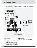
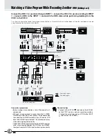
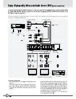
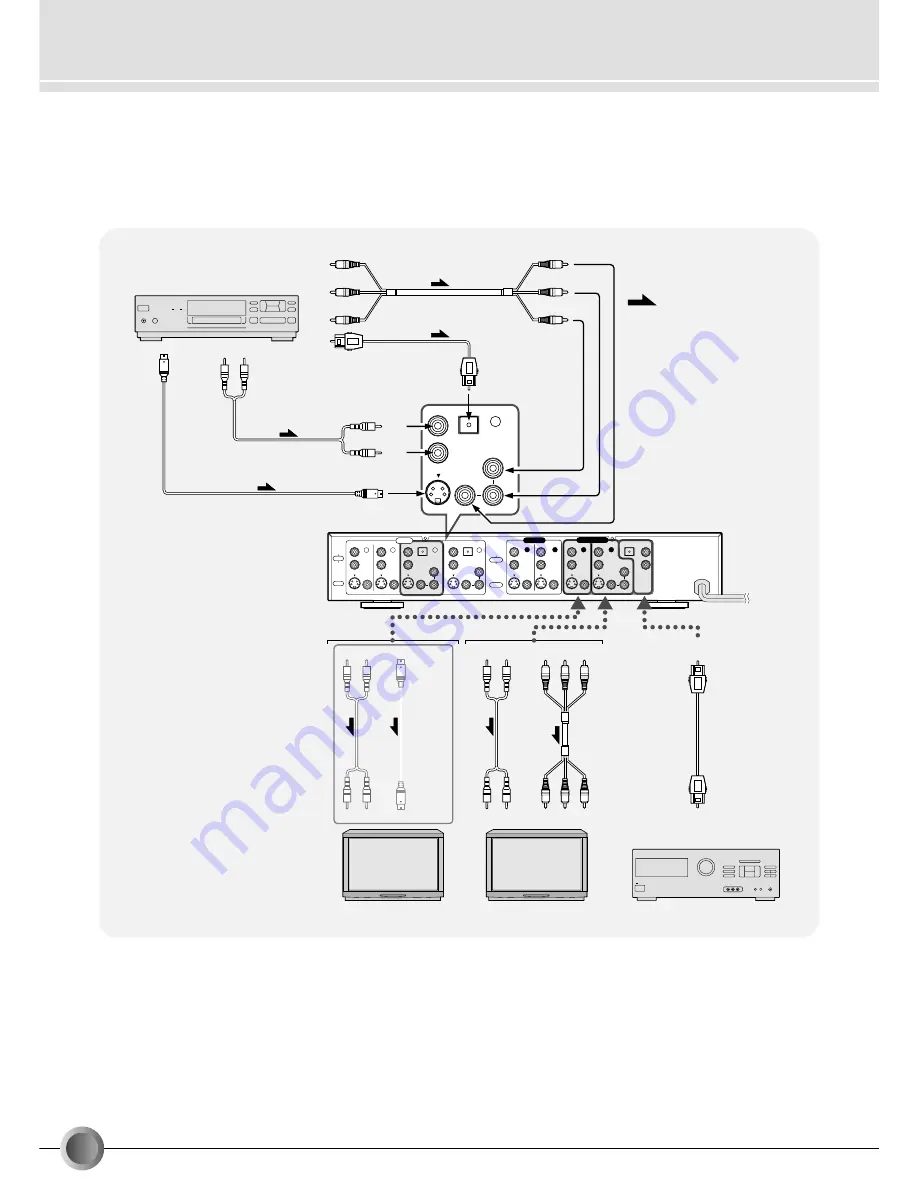
Connect a DVD player to INPUT terminal 

4

, then connect a TV equipped with a component terminal

to the MONITOR OUT 

2

 and connect an AV receiver equipped with an OPTICAL connector to an

OPTICAL output connector.

This shows merely an example of connection. Also refer to the Instruction books of the other components you are using for their
connection and operation procedures.

Enjoy High-quality Video and Audio from a DVD 

(Optical connection)

Connection precautions

• Turn off the power to all components before making con-

nections.

• Even when connection using a component video cord out-

put is used, also connect the S-VIDEO and audio cords.
The audio cannot be output unless an audio cord is con-
nected.

JX-S555 Rear panel

DVD Player (Playback deck)

TV

(white)

(red)

(white)

(red)

(white)

(red)

(g

reen)

(b

lue)

(red)

(g

reen)

(red)

(b

lue)

(white)

(red)

TV

(Equipped with component terminals)

INPUT

1

2

4

5

OUTPUT

1

2

AUDIO

RIGHT

LEFT

VIDEO

1

2

AUDIO

RIGHT

Cr/Pr

Y

Cb/Pb

Cr/Pr

Y

Cb/Pb

Cr/Pr

Y

Cb/Pb

LEFT

OPTICAL

OPTICAL

OPTICAL

MONITOR OUT

AUDIO

RIGHT

LEFT

4

Cr/Pr

Y

Cb/Pb

OPTICAL

VIDEO

VICTOR COMPANY OF JAPAN, LIMITED.   MADE IN JAPAN

AVIS : RISQUE DE CHOC ELECTRIQUE-NE PAS OUVRIR

WARNING : SHOCK HAZARD-DO NOT OPEN

AV receiver

To 

AUDIO 

Output 

To

S-VIDEO

Output

(white)

(red)

 : Signals

(green)

(blue)

(red)

To Component Output

To Component Output

To Digital AUDIO Output

To

S-VIDEO

Input

To
AUDIO
Input

(white)

(red)

To 
Component 
Input

To 
AUDIO 
Input 

(green)

(blue)

(red)

• The video signals from the VIDEO component input at IN-

PUT 

4

 and 

5

 are output only at the component video out-

put terminals of MONITOR OUT 

2

. The video signals are

not converted into composite video and S-VIDEO signals.

• The OPTICAL signal from INPUT 

4

5

 can only be out-

put to the AUDIO MONITOR OUT OPTICAL connector. It
is not converted to an analog AUDIO signal.

• To watch the video input to INPUT 

1

 - 

3

 , also connect a

TV to the MONITOR OUT 

1

.

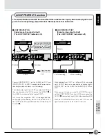
Summary of Contents for JX-B555

Page 1: ... POWER REMOTE CONTROL UNIT FOR JX S555 RM AJ555 SOURCE SELECT DUBBING LOCK LOOP PROTECT MONITOR SELECT AV SELECTOR J5500 105A For Customer Use Enter below the Serial No which is located on the rear or bottom of cabinet Retain this information for future reference Model No JX S555 Serial No ENGLISH INTRODUCTION BASIC OPERATION ADVANCED OPERATION OTHERS FRANÇAIS ESPAÑOL AV SELECTOR SELECTEUR AV SELE...

Page 2: ...érique de la classe B respecte toutes les exigences du Réglement sur le matérier brouilleur du Canada WARNING TO REDUCE THE RISK OF FIRE OR ELECTRIC SHOCK DO NOT EXPOSE THIS APPLIANCE TO RAIN OR MOISTURE CAUTION RISK OF ELECTRIC SHOCK DO NOT OPEN CAUTION TO REDUCE THE RISK OF ELECTRIC SHOCK DO NOT REMOVE COVER OR BACK NO USER SERVICEABLE PARTS INSIDE REFER SERVICING TO QUALIFIED SERVICE PERSONNEL ...

Page 3: ...ecording Another one Dubbing Lock 14 Enjoy High Quality Video and Audio from a DVD Optical connection 16 Useful Tips 18 S VIDEO input output connectors 18 Y C separator 18 Y C mixer 18 LOOP PROTECT function 19 DUBBING LOCK button 20 Component terminals 21 OPTICAL connector 21 Check the contents This unit JX S555 Remote control unit RM AJ555 Battery AA x 2 for operation testing Warranty card Regist...

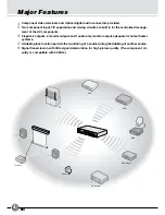
Page 4: ...adequate for home theater systems 4 A dubbing lock function permits the monitoring of a source during the dubbing of another source 5 Signal transmission with little signal deterioration for high picture quality The component cir cuitry is compatible with 30 MHz Major Features TV DBS AV receiver DVD player Projector VCR VCR Camcorder STANDB Y SOURC E SELECT DUBBIN G LOCK MONIT OR SELECT LOOP PROTE...

Page 5: ...1 2 AUDIO RIGHT LEFT VIDEO 1 2 AUDIO RIGHT Cr Pr Y Cb Pb Cr Pr Y Cb Pb Cr Pr Y Cb Pb LEFT OPTICAL OPTICAL OPTICAL MONITOR OUT AUDIO RIGHT LEFT VIDEO VICTOR COMPANY OF JAPAN LIMITED MADE IN JAPAN AVIS RISQUE DE CHOC ELECTRIQUE NE PAS OUVRIR WARNING SHOCK HAZARD DO NOT OPEN S VIDEO VIDEO AUDIO L R Camcorder Analog output INPUT 3 The AV Selector Expands the Dimensions of the AV World The AV Selector ...

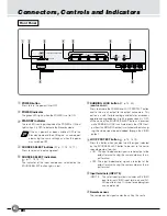
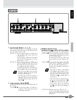
Page 6: ...ring dubbing It lights in green when it is ON When one of the SOURCE SELECT buttons is pressed while DUBBING LOCK is activated only the VIDEO out put from the MONITOR output is switched without chang ing the video signal being dubbed through the VIDEO output 7 LOOP PROTECT button p 13 15 19 Press this button when you don t want the signal selected by the SOURCE SELECT button to be sent to the corr...

Page 7: ... output terminals 3 MONITOR output terminals MONITOR OUT 1 2 AUDIO OPTICAL digital Connect the monitor output components to these outputs MONITOR 1 This set of terminals includes an S VIDEO output terminal VIDEO output terminal and an AUDIO output terminal Connect to the S VIDEO or VIDEO input terminal and AUDIO input connector on a TV MONITOR 2 This set of terminals includes an S VIDEO output ter...

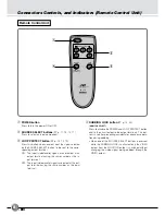
Page 8: ...g the same number as the input terminal Connectors Controls and Indicators Remote Control Unit Remote Control Unit 4 DUBBING LOCK button p 14 20 MONITOR SELECT Press to disable the POWER and LOOP PROTECT button and fix the circuit output to the output terminals This but ton is useful for preventing accidental or erroneous opera tion during dubbing When one of the SOURCE SELECT buttons is pressed w...

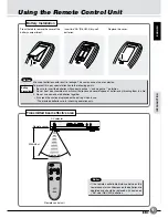
Page 9: ... in use The provided batteries are for checking operation only Press the tab to remove the cover of the battery compartment Insert two AA R6 UM 3 dry cell batteries Replace the cover Battery Installation Battery Precautions Transmitted beam effective area If the remote controllable distance between the remote and main unit decreases the batteries are depleted and should be replaced with new ones A...

Page 10: ...the JX S555 the signal from the S VIDEO input terminal is given prior ity Connection tips Connect to the OUTPUT terminals on the JX S555 so that the VCR can be used as a recording machine INPUT 1 2 4 5 OUTPUT 1 2 AUDIO RIGHT LEFT VIDEO 1 2 AUDIO RIGHT Cr Pr Y Cb Pb Cr Pr Y Cb Pb Cr Pr Y Cb Pb LEFT OPTICAL OPTICAL OPTICAL MONITOR OUT AUDIO RIGHT LEFT VIDEO VICTOR COMPANY OF JAPAN LIMITED MADE IN JA...

Page 11: ...nals on the JX S555 4 Turn on theVCR s power and start playback Set the LOOP PROTECT button to ON p 19 You can not operate the POWER and LOOP PROTECT buttons when the DUBBING LOCK button is pressed p 20 MEMO When you want to watch a video on another VCR press the SOURCE SELECT button to select the line number that the VCR is connected to Notes STANDBY SOURCE SELECT DUBBING LOCK MONITOR SELECT LOOP...

Page 12: ...ing it to the S VIDEO terminal If both the S VIDEO input terminal and the VIDEO input terminal are connected between theVCR and the JX S555 the signal from the S VIDEO input terminal is given prior ity INPUT 1 2 4 5 OUTPUT 1 2 AUDIO RIGHT LEFT VIDEO 1 2 AUDIO RIGHT Cr Pr Y Cb Pb Cr Pr Y Cb Pb Cr Pr Y Cb Pb LEFT OPTICAL OPTICAL OPTICAL MONITOR OUT AUDIO RIGHT LEFT VIDEO VICTOR COMPANY OF JAPAN LIMI...

Page 13: ...tart recording on VCR 2 Notes Set the input switch on the recording VCR to the external input mode AUX when dubbing Set the recording VCR to S VIDEO input when using an S VIDEO input terminal for recording Notes MEMO Preparation STANDBY SOURCE SELECT DUBBING LOCK MONITOR SELECT LOOP PROTECT S VIDEO INPUT 3 VIDEO AUDIO L R POWER JX S555 AV SELECTOR 1 2 3 4 5 POWER REMOTE CONTROL UNIT FOR JX S555 RM...

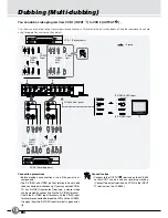
Page 14: ... the S VIDEO input terminal is given priority Connection tips Connect to the OUTPUT 1 terminals on the JX S555 so that VCR 1 can be used as a recording machine Connect the output terminals on VCR 2 to the INPUT 2 terminals on the JX S555 INPUT 1 2 4 5 OUTPUT 1 2 AUDIO RIGHT LEFT VIDEO 1 2 AUDIO RIGHT Cr Pr Y Cb Pb Cr Pr Y Cb Pb Cr Pr Y Cb Pb LEFT OPTICAL OPTICAL OPTICAL MONITOR OUT AUDIO RIGHT LEF...

Page 15: ...f the DBS The SOURCE SELECT 5 indicator lights in red The DBS video is displayed on the TV screen Preparation When the input source is changed by pressing one of the SOURCE SELECT buttons in the dubbing lock mode the video displayed on the TV connected to the MONITOR OUT can be changed without affecting the video being dubbed MEMO STANDBY SOURCE SELECT DUBBING LOCK MONITOR SELECT LOOP PROTECT S VI...

Page 16: ...uipped with component terminals INPUT 1 2 4 5 OUTPUT 1 2 AUDIO RIGHT LEFT VIDEO 1 2 AUDIO RIGHT Cr Pr Y Cb Pb Cr Pr Y Cb Pb Cr Pr Y Cb Pb LEFT OPTICAL OPTICAL OPTICAL MONITOR OUT AUDIO RIGHT LEFT 4 Cr Pr Y Cb Pb OPTICAL VIDEO VICTOR COMPANY OF JAPAN LIMITED MADE IN JAPAN AVIS RISQUE DE CHOC ELECTRIQUE NE PAS OUVRIR WARNING SHOCK HAZARD DO NOT OPEN AV receiver To AUDIO Output To S VIDEO Output whit...

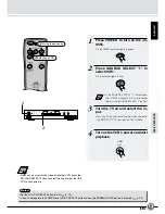
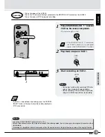
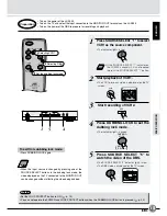
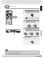
Page 17: ...e TV screen Preparation STANDBY SOURCE SELECT DUBBING LOCK MONITOR SELECT LOOP PROTECT S VIDEO INPUT 3 VIDEO AUDIO L R POWER JX S555 AV SELECTOR 1 2 3 4 5 POWER REMOTE CONTROL UNIT FOR JX S555 RM AJ555 SOURCE SELECT DUBBING LOCK LOOP PROTECT MONITOR SELECT AV SELECTOR 1 1 Selecting the DVD player POWER TV INPUT SELECT TV POWER SOURCE SELECT DIGITAL SURROUND PLAY DVD Some DVD software contains reco...

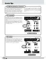
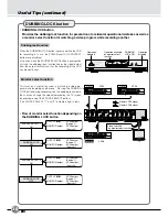
Page 18: ... termi nals separate signals into a composite video signal This feature is convenient in dubbing from a VCR equipped with S VIDEO terminals to a VCR without them VCR without an S VIDEO output VCR with an S VIDEO input Signals Example of Y C Separator INPUT 1 2 4 5 OUTPUT 1 2 AUDIO RIGHT LEFT VIDEO 1 2 AUDIO RIGHT Cr Pr Y Cb Pb Cr Pr Y Cb Pb Cr Pr Y Cb Pb LEFT OPTICAL OPTICAL OPTICAL MONITOR OUT AU...

Page 19: ...UT terminals is required when connecting IN PUT OUTPUT 1 on the JX S555 to the INPUT OUTPUT on VCR 1 When you want to extend a set of the OUTPUT terminals set the LOOP PROTECT function to OFF and connect the OUTPUT 1 terminals on the JX S555 to the recording VCR When the LOOP PROTECT function is set to OFF the same signal can be output to all the OUTPUT terminals VCR 2 Playback Recording Playback ...

Page 20: ... SOURCE SELECT 1 ON DUBBING LOCK ON SOURCE SELECT 4 ON DUBBING LOCK OFF OUTPUT 1 2 VCR1 output Source 1 MONITOR output VCR1 output Source 1 OUTPUT 1 2 VCR1 output Source 1 MONITOR output VCR1 output Source 1 OUTPUT 1 2 VCR1 output Source 1 MONITOR output VCR2 output Source 4 OUTPUT 1 2 VCR1 output Source 1 MONITOR output VCR1 output Source 1 Dubbing lock function When the DUBBING LOCK button is pr...

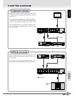
Page 21: ...layer or DBS to an MD recorder using the JX S555 s OPTI CAL connector An OPTICAL connector outputs the digital audio from a DVD player or DBS as an optical signal to maintain its purity Signals INPUT 1 2 4 5 OUTPUT 1 2 AUDIO RIGHT LEFT VIDEO 1 2 AUDIO RIGHT Cr Pr Y Cb Pb Cr Pr Y Cb Pb Cr Pr Y Cb Pb LEFT OPTICAL OPTICAL OPTICAL MONITOR OUT AUDIO RIGHT LEFT VIDEO VICTOR COMPANY OF JAPAN LIMITED MADE...

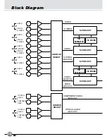
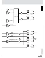
Page 22: ...IXER AUDIO S VIDEO VIDEO VIDEO MONITOR S VIDEO MONITOR AUDIO MONITOR SOURCE SELECT COMPONENT VIDEO MONITOR AUDIO AUDIO AUDIO AUDIO VIDEO S VIDEO VIDEO S VIDEO S VIDEO S VIDEO OPTICAL AUDIO INPUT4 INPUT5 COMPONENT VIDEO OPTICAL AUDIO COMPONENT VIDEO OPTICAL AUDIO MONITOR S V SELECT S V SELECT S V SELECT Y C SEPARATOR Y C MIXER ...

Page 23: ...OUTPUT1 OUTPUT2 MONITOR OUTPUT1 MONITOR OUTPUT2 6 dB 6 dB 6 dB 6 dB 6 dB LOOP PROTECT OPTICAL AUDIO COMPONENT VIDEO AUDIO VIDEO S VIDEO AUDIO VIDEO S VIDEO AUDIO VIDEO S VIDEO AUDIO S VIDEO AUDIO AUDIO COMPONENT VIDEO MONITOR VIDEO MONITOR AUDIO MONITOR VIDEO S VIDEO MONITOR AUDIO S VIDEO ...

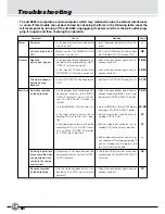
Page 24: ...ition Recording No picture recorded on the edited tape Check the connections again and re connect correctly before s e l e c t i n g the correct SOURCE SELECT button Press DUBBING LOCK to OFF before pressing a SOURCE SELECT button Set the input select switch on the re cording VCR to AUX Set the video input switch on the re cording VCR to the correct position Some video software may contain sig nal...

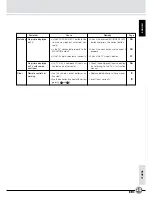
Page 25: ...ressed SOURCE SELECT button and press the correct button Check the connection and connect it properly Check the TV s input selector 10 10 11 9 9 Other Remote control not working Are the remote control batteries ex hausted Are the batteries inserted with correct polarity and Replace both batteries with new ones Insert them correctly No picture displayed on TV with compo nent input Is a TV with a co...

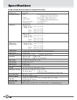
Page 26: ...Component signals 30 MHz Reference level 10 dBV 47 kΩ Maximum level 6 dBV 1 kHz 1 distortion 10 dBV with reference input 1 kHz 80 dB or more 1 kHz 80 dB or more 5 Hz to 50 kHz Less than 0 03 with reference input 1 kHz Peak emission wavelength 660 nm 30 nm Peak output power 15 dBm to 21 dBm at the output end of the reference optical fiber cable AC 120 V 60 Hz 13 W 2 0 W in Standby mode W 435 mm x H...

Page 27: ...fewer blurs in the colors Composite video signal Signal composed of the luminance Y and chrominance C signals of the S Video signals Component terminals Means for transmission of high quality video signals Y Pb Pr and Y Cb Cr from a DVD player etc to a high per formance video monitor without interference between the signal components OPTICAL digital connector Means for transmission of high quality...

Page 28: ...erminals 7 21 27 Composite video signal 7 27 D DUBBING LOCK 6 8 15 20 L LOOP PROTECT 6 8 19 M MULTI DUBBING 12 O OPTICAL CONNECTOR 16 21 S STANDBY 6 SOURCE SELECT 6 8 S VIDEO signal 7 27 Y Y C separator 18 Y C mixer 18 Terms Index ...

Page 29: ...J VC VICTOR COMPANY OF JAPAN LIMITED Printed in Japan 䊚 2001 VICTOR COMPANY OF JAPAN LIMITED ...

Reviews: