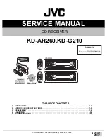


SERVICE MANUAL
COPYRIGHT © 2004 Victor Company of Japan, Limited
No.MA111
2004/11
CD RECEIVER
MA111
2004
11
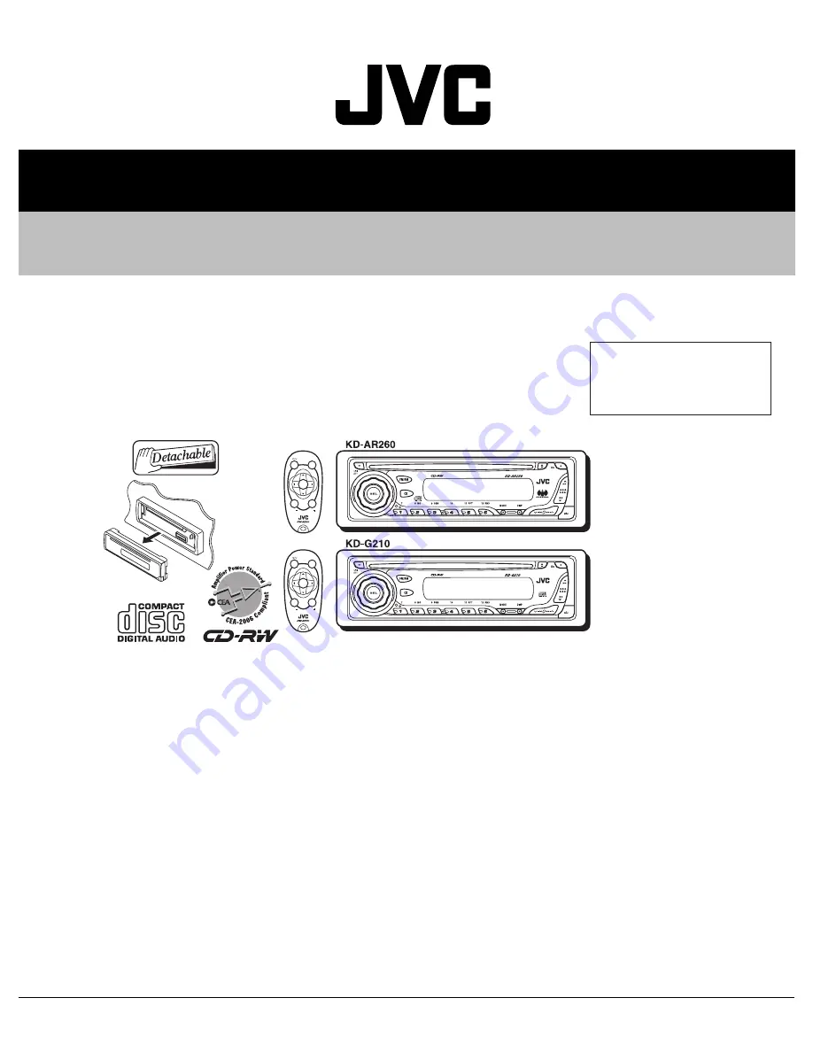
KD-AR260,KD-G210
TABLE OF CONTENTS
1
PRECAUTIONS . . . . . . . . . . . . . . . . . . . . . . . . . . . . . . . . . . . . . . . . . . . . . . . . . . . . . . . . . . . . . . . . . . . . . . . 1-3
2
SPECIFIC SERVICE INSTRUCTIONS . . . . . . . . . . . . . . . . . . . . . . . . . . . . . . . . . . . . . . . . . . . . . . . . . . . . . . 1-5
3
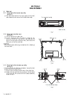
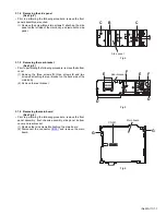
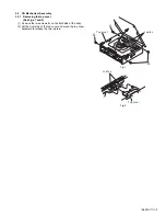
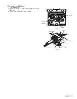
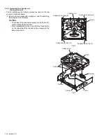
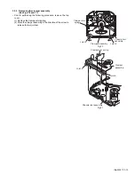
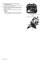
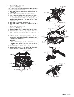
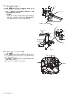
DISASSEMBLY . . . . . . . . . . . . . . . . . . . . . . . . . . . . . . . . . . . . . . . . . . . . . . . . . . . . . . . . . . . . . . . . . . . . . . . 1-6
4
ADJUSTMENT . . . . . . . . . . . . . . . . . . . . . . . . . . . . . . . . . . . . . . . . . . . . . . . . . . . . . . . . . . . . . . . . . . . . . . . 1-24
5
TROUBLESHOOTING . . . . . . . . . . . . . . . . . . . . . . . . . . . . . . . . . . . . . . . . . . . . . . . . . . . . . . . . . . . . . . . . . 1-25
SOUND
VOL
VOL
SOURCE
R
F
U
D
ATT
SOUND
VOL
VOL
SOURCE
R
F
U
D
ATT
Area suffix
J ------------- Northern America
Summary of Contents for KD-AR260
Page 29: ... No MA111 1 29 ...
Page 97: ...3 11 MEMO ...


