background image

SERVICE MANUAL

COPYRIGHT © 2008 Victor Company of Japan, Limited

No.MA425<Rev.001>

2008/12

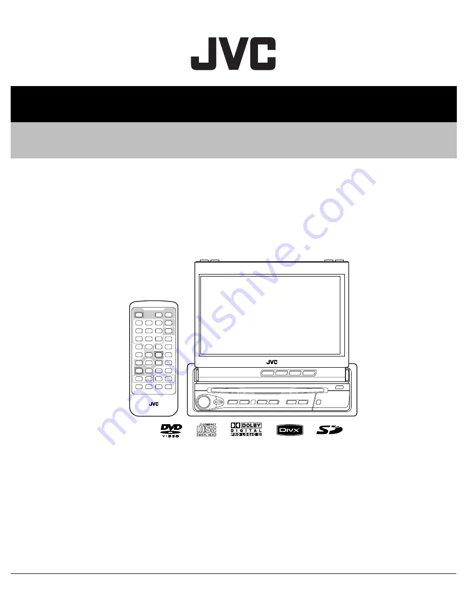
DVD RECEIVER WITH MONITOR

MA425<Rev.001>

2008

12

SERVICE MANUAL

KD-AV7100JW, KD-AV7100EU, 

KD-AV7100EE, KD-AV7100U, 

KD-AV7100US, KD-AV7100A

COPYRIGHT © 2008 Victor Company of Japan, Limited

Lead free solder used in the board (material : Sn-Cu, melting point : 230 Centigrade)

TABLE OF CONTENTS

1

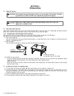
PRECAUTION. . . . . . . . . . . . . . . . . . . . . . . . . . . . . . . . . . . . . . . . . . . . . . . . . . . . . . . . . . . . . . . . . . . . . . . . .  1-4

2

SPECIFIC SERVICE INSTRUCTIONS . . . . . . . . . . . . . . . . . . . . . . . . . . . . . . . . . . . . . . . . . . . . . . . . . . . . . .  1-6

3

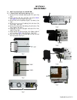
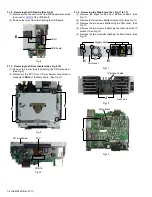
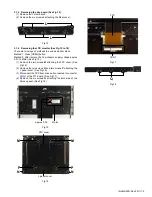
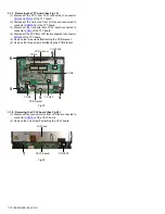
DISASSEMBLY  . . . . . . . . . . . . . . . . . . . . . . . . . . . . . . . . . . . . . . . . . . . . . . . . . . . . . . . . . . . . . . . . . . . . . . .  1-7

4

ADJUSTMENT . . . . . . . . . . . . . . . . . . . . . . . . . . . . . . . . . . . . . . . . . . . . . . . . . . . . . . . . . . . . . . . . . . . . . . .  1-11
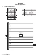
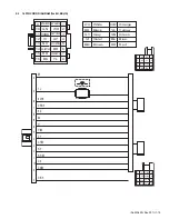
5

TROUBLESHOOTING . . . . . . . . . . . . . . . . . . . . . . . . . . . . . . . . . . . . . . . . . . . . . . . . . . . . . . . . . . . . . . . . .  1-14

Summary of Contents for KD-AV7100A

Page 1: ...RVICE MANUAL KD AV7100JW KD AV7100EU KD AV7100EE KD AV7100U KD AV7100US KD AV7100A COPYRIGHT 2008 Victor Company of Japan Limited Lead free solder used in the board material Sn Cu melting point 230 Centigrade TABLE OF CONTENTS 1 PRECAUTION 1 4 2 SPECIFIC SERVICE INSTRUCTIONS 1 6 3 DISASSEMBLY 1 7 4 ADJUSTMENT 1 11 5 TROUBLESHOOTING 1 14 ...

Page 2: ...iary input jack USB input terminal Aerial input Output AV OUT Others iPod OE REMOTE 2 FM AM TUNER Frequency Range USA FM 87 5 MHz 107 9 MHz 200 kHz AM 530 kHz 1 710 kHz 10 kHz S Amer1 FM 87 5 MHz 107 9 MHz 100 kHz AM 530 kHz 1 710 kHz 10 kHz Europe FM 87 50 MHz 108 00 MHz 50 kHz AM 522 kHz 1 620 kHz 9 kHz Other FM 87 50 MHz 108 00 MHz 50 kHz AM 531 kHz 1 602 kHz 9 kHz FM Tuner Usable Sensitivity 1...

Page 3: ...ent Less than 500 mA 5 V MONITOR Screen Size 7 inch wide liquid crystal display Number of Pixel 336 960 pixels 480 x 3 horizontal 234 vertical Drive Method TFT Thin Film Transistor active matrix format Color System NTSC PAL for Spanish NTSC Aspect Ratio 16 9 wide GENERAL Power Requirement Operating Voltage DC 14 4 V 11 V to 16 V allowance Grounding System Negative ground Allowable Storage Temperat...

Page 4: ...ter replacement return the shorted parts to their original condition Refer to the text Do not use a tester to check the condition of the laser diode in the optical pickup The tester s internal power source can easily destroy the laser diode 1 3 Handling the traverse unit optical pickup 1 Do not subject the traverse unit optical pickup to strong shocks as it is a sensitive complex unit 2 Cut off th...

Page 5: ...oduct uses visible and or invisible laser radiation and is equipped with safety switches which prevent emission of radiation when the drawer is open and the safety interlocks have failed or are defeated It is dangerous to defeat the safety switches 5 CAUTION If safety switches malfunction the laser is able to function 6 CAUTION Use of controls adjustments or performance of procedures other than th...

Page 6: ...1 6 No MA425 Rev 001 SECTION 2 SPECIFIC SERVICE INSTRUCTIONS This service manual does not describe SPECIFIC SERVICE INSTRUCTIONS ...

Page 7: ...p chassis See Fig 3 4 Remove the four screws C attaching the both side of the Top chassis See Fig 4 5 Remove the two screws D attaching the both side of the Front chassis See Fig 4 6 Disengage two hooks a engaged both side of the Front chassis See Fig 5 7 Disconnect the connector wire from Front chassis connect ed to connector CON2 of the USB board See Fig 6 8 Tear off an FPC from a CD mechanism a...

Page 8: ...cted to connector CON16 of the Main board See Fig 10 Fig 9 Fig 10 3 1 4 Removing the Main board See Fig 11 to 13 1 Remove the Signal cables from Bottom chassis See Fig 11 2 Remove the two screws G attaching the FAN See Fig 11 3 Remove the two screws H attaching the FAN cover See Fig 11 4 Remove the two screws J attaching the Heat sink with IC bracket See Fig 12 5 Remove the two screws K attaching ...

Page 9: ...ter remove the Top chassis supply voltage approx 3 0V to Motor See Fig 15 1 Remove the two screws M attaching the FPC cover See Fig 16 2 Remove the two screws N and two screws P attaching the L panel cover See Fig 16 3 Disconnect the FPC from drive unit connected to connector CON1 of the TFT board See Fig 17 4 Remove the six screws Q attaching the both side of the Screen panel See Fig 18 Fig 15 Fi...

Page 10: ...r CON5 of the TFT board 4 Disconnect the FPC from LCD lens connected to connector CON20 of the TFT board 5 Remove the two screws R attaching the PCB bracket 6 Remove the three screws S attaching the PCB bracket Fig 19 3 1 8 Removing the CCLF board See Fig 20 1 Disconnect the connector wire from LCD lens connected to connector CON102 of the CCLF board 2 Remove the one screw T attaching the CCLF boa...

Page 11: ...Level Line out 2 5V Vol MAX 4 1 4 Dummy load Exclusive dummy load should be used for AM and FM For FM dummy load there is a loss of 6dB between SSG output and an tenna input The loss of 6dB need not be considered since direct reading of figures are applied in this working standard 4 1 5 How to connect the extension cable for adjusting Be sure to attach the heat sink and rear bracket onto the power...

Page 12: ...t control Power save 18 CLOR 80 FF A0 Adjust Color control Chroma trap filter for Y input 19 TINT 00 FF A0 Adjust Tint control Base Band TINT RGB input coupling mode 20 SHAP 00 FF 30 Adjust Comb filter for base band color signal of NTSC CW out mode Sharpness control 21 BRT 00 FF 98 Adjust Brightness control 22 SUBC 00 FF 60 Adjust Auto Brightness Limiter start point Auto Brightness Limiter off Aut...

Page 13: ...der for the Dot clock output signal DOTCLK adjustment 36 PADJ 10 FF 20 Fix VD phase phase DOTCLK adjustment 37 VPHASE 00 07 00 Adjust VD out Phase 37 HPHASE 00 1F 11 Adjust HD out Phase 38 GM2RGB 00 FF 00 Adjust Gamma2 Gain extension for R G B 39 T1 00 FF 00 Fix For IC testing at plant 40 T2 00 FF 00 Fix For IC testing at plant 41 SID_S 00 FF 02 Fix SECAM Gate pulse phase SECAM ID sensitivity SECA...

Page 14: ...H BK RD VI BK VI BK GY 11 1 13 4 16 12 3 VI WH 5 WH BK 10 GN 9 GN BK GY BK OR WH 15 14 7 BL WH Black RD BK Red BL Blue WH White GN Green GY Gray Yellow VI Violet YL Orange OR 9 10 11 12 8 7 5 13 14 15 16 4 3 2 1 BK RD WH GN VI GY BL WH GN BK VI WH GY BK YL BL WH BK NC 6 OR WH VI BK 2 WH 8 ...

Page 15: ... 9 GN BK GY BK OR WH 15 14 7 BL WH 9 10 11 12 8 7 5 13 14 15 16 4 3 2 1 BK RD WH GN VI GY BL WH GN BK VI WH GY BK YL NC WH BK BR 6 OR WH VI BK 1 3 5 7 2 4 6 8 NC BL WH YL RD BK NC BR OR WH Black RD BK Red BL Blue WH White GN Green GY Gray Yellow VI Violet YL Brown BR Orange OR 1 3 5 7 2 4 6 8 GY WH GY BK GN GN BK VI VI BK WH BK ...

Page 16: ... No MA425 Rev 001 VPT Printed in Japan Victor Company of Japan Limited Mobile Entertainment Division 10 1 1chome Ohwatari machi Maebashi city 371 8543 Japan ...

Reviews: