1-12 (No.MA454<Rev.001>)
3.2
DVD mechanism assembly section
3.2.1 Removing the Traverse mechanism assembly (See
Fig.1 to 6)
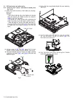
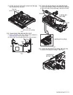
(1) Solder the short land section on the flexible wire of pickup.
(See Fig.1)
Caution:
* Solder the short land section on the flexible wire of pickup
before disconnecting the flexible wire form the connector
CN101
on the Front end board.
If the flexible wire is disconnected without attaching the
solder, the pickup may be destroyed by static electricity.
* When attaching the Traverse mechanism assembly, re-
move the solder from the short land section after connection
the flexible wire to the connector
CN101
on the Front end
board.
Fig.1
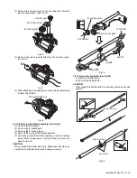
(2) Voltage supply to
TP79
and
TP81
approx DC 3.0V until
Clamper is shift to loading complete position. (See Fig.2)
(3) Disconnect the flexible wires from Traverse mechanism assembly
connected to connector
CN101
and
CN164
of the Front end
board. (See Fig.2)
Fig.2
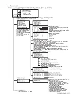
(4) Remove the five screws
A
attaching the Top cover assembly.
(See Fig.3)
Fig.3
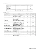
(5) From the bottom side, disconnect the connector wire from
Top cover assembly connected to connector
CN2
of the
Front end board. (See Fig.4)
Fig.4
(6) From the bottom side, remove the spring from Traverse
mechanism assembly. (See Fig.5)
Fig.5
Solder short part
CENTER
R21
D-
DGND_7
R312
R317
WOOFER
TP67
R357
TP79
TP81
TP92
Voltage supply
position
CN164
CN101
TP81
TP79
A
CN2
Summary of Contents for KD-AVX55A
Page 31: ......


