1-14 (No.MA454<Rev.001>)
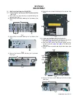
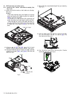
(2) Remove the two screws
C
attaching the Gear base assembly.
(See Fig.10)
Fig.10
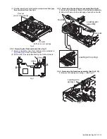
3.2.5 11Removing the Loading arm holder. (See Fig.)
(1) Remove the two screws
D
attaching the Loading arm holder.
(2) Remove the Loading arm spring R.
Fig.11
3.2.6 Removing the Loading moor assembly (See Fig.12)
(1) Remove the three screws
E
attaching the Loading motor
assembly.
Fig.12
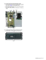
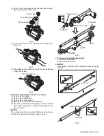
3.2.7 Removing the Slide cam assembly (See Fig.13)
(1) Slide to backward the Slide cam assembly and the remove
the Slide cam spring.
(2) Slide to frontward the slide cam assembly, and then take
out it.
Fig.13
3.2.8 Removing the Photo board (See Fig.14)
(1) Pressing the hook
c
and then slide to backward (slide to the
arrow side) the Disc plate.
(2) Remove the one screw
F
attaching the Photo board.
Fig.14
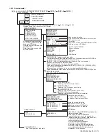
3.2.9 Removing the Loading motor (See Fig.15 to 18)
(1) Remove the A wheel gear. (See Fig.15)
Fig.15
C
D
Loading arm
spring R
Loading arm
holder
E
Slide cam assembly
Slide cam spring
hook
c
hook
c
F
Photo board
A Wheel gear
Summary of Contents for KD-AVX55A
Page 31: ......


