

SERVICE MANUAL
COPYRIGHT © 2008 Victor Company of Japan, Limited
No.MA387<Rev.003>
2008/9
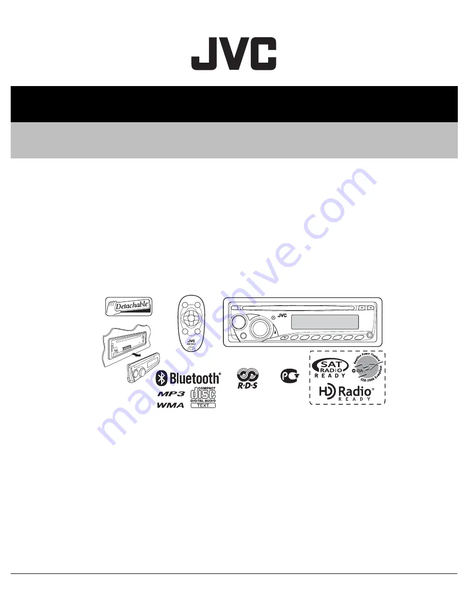
CD RECEIVER
MA387<Rev.003>
2008
9
SERVICE MANUAL
KD-BT11J, KD-BT11E, KD-BT11EX,
KD-BT11EY, KD-BT11EU, KD-BT11EE,
KD-BT11U, KD-BT11UT, KD-BT19UR,
KD-BT12E, KD-BT12EX
COPYRIGHT © 2008 Victor Company of Japan, Limited
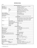
Lead free solder used in the board (material : Sn-Ag-Cu, melting point : 219 Centigrade)
Lead free solder used in the board (material : Sn-Cu, melting point : 230 Centigrade)
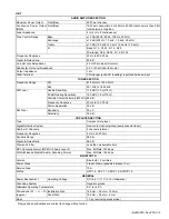
TABLE OF CONTENTS
1
PRECAUTION. . . . . . . . . . . . . . . . . . . . . . . . . . . . . . . . . . . . . . . . . . . . . . . . . . . . . . . . . . . . . . . . . . . . . . . . . 1-6
2
SPECIFIC SERVICE INSTRUCTIONS . . . . . . . . . . . . . . . . . . . . . . . . . . . . . . . . . . . . . . . . . . . . . . . . . . . . . . 1-9
3
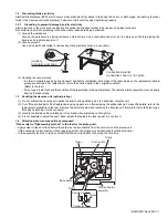
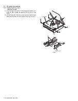
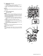
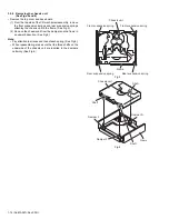
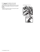
DISASSEMBLY . . . . . . . . . . . . . . . . . . . . . . . . . . . . . . . . . . . . . . . . . . . . . . . . . . . . . . . . . . . . . . . . . . . . . . . 1-9
4
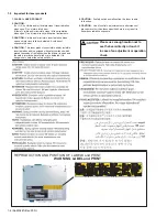
ADJUSTMENT . . . . . . . . . . . . . . . . . . . . . . . . . . . . . . . . . . . . . . . . . . . . . . . . . . . . . . . . . . . . . . . . . . . . . . . 1-25
5
TROUBLESHOOTING . . . . . . . . . . . . . . . . . . . . . . . . . . . . . . . . . . . . . . . . . . . . . . . . . . . . . . . . . . . . . . . . . 1-26
for
E/EX/EY/EU/EE
for EE
for J/U/UT/UR
for J/UR
Summary of Contents for KD-BT11E
Page 29: ... No MA387 Rev 003 1 29 ...
Page 66: ... M E M O ...


