


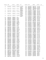
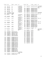


2-2
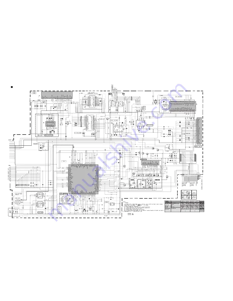
Parts are safety assurance parts.
When replacing those parts make
sure to use the specified one.
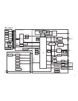
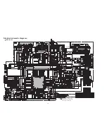
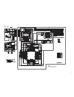
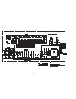
Standard schematic diagrams
Q1
C312
IC801
C783
R738
R812
C711
R739
R740
C311
R734
IC201
L11
C301
J321
CN702
R24
IC701
CN701
R781
C313
R899
IC301
C307
R252
R799
R898
IC161
C173
C902
R804
C314
C303
C304
R814
IC802
R807
C163
R810
R801
R813
R808
IC205
D331
TU1
D321
IC702
R332
R322
C368
C369
C160
C170
C320
L701
C316
C319
C892
R5
IC361
D301
D783
C317
R797
R742
TM
TXM
C381
R361
R362
R366
R386
IC203
Q902
C256
R220
R744
VSS
R783
R753
R720
R745
R719
R722
C243
R385
R723
R365
X701
R382
RXM
IC202
X1
C706
R241
Q332
Q322
D203
D204
R253
R172
R381
R242
R741
D998
R728
R756
X702
D997
D996
D995
R706
C891
R891
C968
C966
C967
C965
C964
R977
R976
C963
C962
C961
CN901
Q712
Q711
C707
Q977
C302
D712
D994
D993
D992
D991
R232
C713
C315
C204
C371
C205
C206
R230
C322
C323
C324
C325
R352
R342
R707
C326
J1
Q784
D782
Q891
C318
C370
D351
R737
R882
R757
D713
R218
C712
D971
Q881
D714
S703
R764
IC771
C771
R201
J801
C372
C361
R178
R91
R81
R74
R72
R179
C362
C382
C207
R931
Q301
R305
C172
C162
R308
C166
C161
C171
C165
C164
R202
C366
C385
C365
C386
R203
C260
IC901
R221
R231
R240
R851
C230
C240
C241
R724
C231
R214
L201
D302
D304
D303
R6
C723
C722
D202
R791
R792
D201
R793
CN201
R721
Q841
R841
R2
R1
L2
c180
C914
C7
C6
c181
D852
L901
R907
R777
C715
C81
C91
D701
D851
C5
R16
C906
IC204
R735
R736
D709
D722
R805
C716
C916
R751
R806
R811
R809
R802
R784
R803
R785
R786
R787
C910
C905
C911
DEBUGCLK
R790
R331
R321
D708
R333
R323
C321
R180
TOOL0
Q934
Q892
R181
C903
C801
R893
C169
D723
D703
R748
C367
R749
FLMDO
C732
D720
C919
D721
R761
R798
R282
Q782
R272
R750
D892
R743
R746
D972
C907
R905
R904
R243
VDD
R758
R371
R932
C920
R239
R227
C918
RESET
R776
C901
R250
R251
C257
C213
R215
R228
D903
C176
R226
R972
C701
C702
C220
C703
C704
C718
D891
R892
C217
R714
C913
C710
C218
D705
D707
D702
D704
D706
R715
R716
R971
C216
R705
C717
D784
C912
R205
R204
D901
R903
R902
R901
C784
Q781
R341
R351
R353
R343
C208
Q976
C904
C915
R752
D341
R766
R767
R704
C708
C705
R701
C709
C971
C341
R754
R755
C881
C215
C251
R771
R732
R779
R881
R717
R718
R713
C254
R175
R778
R759
R82
C3
C78
R92
C22
C21
IC71
D1
D2
R21
C72
C76
C71
C75
C74
X71
R73
C203
C73
R75
C77
C4
R22
R372
R374
R373
Q252
R774
R206
Q933
R730
R306
R176
R177
C177
C167
C168
R367
C219
R363
R387
R383
C212
C255
R225
R222
R208
R712
R772
R12
R11
R14
R13
R10
R15
R9
R3
R7
C851
C852
R213
C253
C252
R229
C201
R219
R212
C202
L702
C714
R247
R4
C8
BT.MOSI
BT.CSB
BT.CLK
BT.MISO
BT.VDD
BT.GND
C841
BZ841
C13
C14
C11
C12
L3
RT1N141C-X
QFV91HJ-474Z
TC7WT241FU-X
0.01
0
10K
330/6.3
4.7k
MA22D23-X
4.7k
QFV91HJ-474Z
1.5K
NAU0004-001
4.7u
QFV91HJ-474Z
QNS0283-001
0
UPD78F1167GC
QGZ1601J1-15
47K
UDZW6.2B-X
100p
82K
TB2926AHQ
47/16
10K
39K
82K
TDA7719-X
1/50
2.2/50
3.9K
100p
100p
100p
0
TC7WT241FU-X
10K
1/50
100
3.9K
1K
100
QMFZ063-150-J1
BD33KA5FP-X
1SS355W-X
1SS355W-X
S-80833CNNB-G-W
820
820
220/10
47/6.3
1/50
1/50
0.022
4.7u
4.7/50
0.022
0.1
8.2K
UDZW6.2B-X
NJM2792V-X
UDZW6.2B-X
UDZW6.2B-X
UDZW6.2B-X
MC2836-X
47/16
8.2K
100
4.7/25
33k
22k
22k
22k
NJM4565V-X
RT1N141C-X
390P
33K
10K
10K
47k
5.6K
10K
0
22K
0.033
33k
4.7K
33k
QAX0916-001Z
22k
NJM4565V-X
0.047
18K
IMX9-W
IMX9-W
UDZW5.6B-X
UDZW5.6B-X
10K
10K
33k
100
100
MA22D23-X
100
47k
QAX0401-001
MA22D23-X
MA22D23-X
MA22D23-X
47k
0.1
1k
100P
100P
100P
100P
100P
12k
27k
100P
100P
100P
QNZ0611-001
RT1N141C-X
RT1P141C-X
0.047
ISA1530SC1/R/-X
QFV91HJ-474Z
UDZW6.2B-X
MA22D23-X
MA22D23-X
MA22D23-X
MA22D23-X
100
0.01
2.2/50
100P
0.1
100P
22P
18K
0.0047
0.0047
0.0047
0.0047
820
820
47k
4.7/50
RT1P141C-X
1SS355W-X
RT1N141C-X
4.7/50
0.0015
1SS355W-X
0
4.7K
2.2k
1SS355W-X
47K
0.01
CRS03-W
RT1N141C-X
UDZW5.6B-X
QSW0648-001Z
100
S-24CS16A0I-G-X
0.047
0
QNZ0095-001
4.7/25
10K
100
2.2K
10K
4.7/25
4.7/25
0.033
47k
RT1N141C-X
1K
2.2/50
2.2/50
270
1/50
1/50
1/50
1/50
1/50
0
4.7/50
4.7/50
4.7/50
4.7/50
0
4.7/50
AN34001A
10K
18K
18K
4.7/50
4.7/50
4.7/50
270
4.7/50
8.2K
47u
UDZW6.2B-X
UDZW6.2B-X UDZW6.2B-X
33K
0.1
680P
UDZW5.6B-X
NQR0007-002X
NQR0007-002X
UDZW5.6B-X
NQR0007-002X
QGA1002C1-02X
5.6K
RT1N141C-X
3.3K
0
0
NQL553J-27NX
0.0047
100/16
0.22
0.1
0.0047
QQR1809-001
68K
47k
0.1
QTE1H57-105Z
QTE1H57-105Z
UDZW6.2B-X
MA22D39-X
0.1
3.3k
0.01
S-24CS16A0I-G-X
1.5K
1.5K
UDZW6.2B-X
6.8K
0.1
0.01
10k
100K
47K
47K
6.8K
100
100K
100
100
100
10/16
47/16
0.1
5.6K
2.2k
2.2k
UDZW6.2B-X
100
100
0.01
47K
RT1N141C-X
RT1N141C-X
47K
47/16
0.047
3.3K
10/16
UDZW6.2B-X
47k
220/10
47k
0.47
10/16
470
3.9K
0
DTC143TKA-X
0
2.2K
1SS355W-X
10K
2.2K
MA22D39-X
220/10
10K
1K
330
4.7K
0
1K
47/16
47K
47K
0.01
47k
2700/16
270
270
0.047
47/16
8.2K
47K
GS1J-X
0.1
10K
2.2k
22P
27P
120P
27P
8P
100P
1SS355W-X
47k
120P
10k
10/16
47/6.3
120P
UDZW6.2B-X
UDZW6.2B-X
UDZW6.2B-X
UDZW6.2B-X
UDZW6.2B-X
100
100
2.2k
22/16
47k
0.1
UDZW11B-X
0.01
0
0
1N5401-F64
4.7k
9.1k
1k
100/16
RT1P141C-X
2.2k
2.2k
100
100
QNB0190-001
390P
RT1N141C-X
10/16
0.1
47k
1SS355W-X
2.2k
22k
47k
0.047
0.047
47k
0.01
0.1
0.047
0
10M
22/16
10/16
10/16
270
4.3K
4.7K
47K
10k
10k
100
22/16
0.0015
2.2K
4.7K
47k
5.1K
0.1
0.01
5.1K
47/16
220/10
LC72725KM-X
1SS355W-X
1SS355W-X
12
0.022
0.01
560p
33p
33p
QAX0926-001Z
2.2k
10/16
2.2/50
2K
47/6.3
0.1
12
0
0
0
RT1P141C-X
47K
20K
2SA1365/F/-X
27k
1K
2.2K
33
QTE1C57-106Z
0.0047
QTE1A57-107Z
47k
120P
47k
47k
47k
0.1
4.7/50
10K
10K
1.2K
100
270
330
4.7k
330
4.7k
47k
1K
10k
1K
3.3K
10/16
4.7K
0.22
1.2K
4.7/50
4.7/50
47K
10/16
47K
8.2K
0.047
4.7u
0.1
330
68K
33p
1/50
QAN0023-001Z
0.1
0.1
0.1
0.1
NQL553J-27NX
LCDSCK
CD.R
PSW
CD.L
CH.R
SW1
SW2
LM0
LM1
RR+
FSU
Q-OUT
BUS0
RFOK
CH.L
FL-
BUS1
9V
BUS2
OUTRL
BUSINT
CD.R
DIM
BUS3
KEY0
BUCK
BUSSCK
/CCE
/RST
REQ
CDON
SRAMSTB
KEY2
BTOUT.L+
KEY1
STEERING
AMPSW
LCDDA
BUS-I/O
FR+
VOL2
SRAMSTB
RR-
LCDCE
LCDCE
BT-
STEERING
CD.L
CH.L
CH.R
VOL1
BUZZER
VOLDA
BT.L
FR-
AFS
BT.R
REMOCON
DIM
OUTFR
AUX.L
OUTRR
AUX.R
AUX.G
FL+
OUTFL
OUTFL
OUTRL
RL-
RL+
OUTSWL
OUTSWR
BT+3.3V
BT+3.3V
BUZZER
BUSSI
BTRST
BUS-I/O
BUSSO
KEY1
GND
BUSSO
CDON
A001158
KEY2
BTOUT.L-
BT.L
BTOUT.R-
BTOUT.R+
BT.R
BT_RX
BT_TX
BTRST
AUX.G
AUX.R
BT+
AUX.L
OUTFR
BUSSCK
OUTRR
SUBMUTE
PS2
BUSSI
VOLMUTE
SSTOP
AFS
CD_8V
MUTE
VOLCK
RDSDA
SWL.4V
VOLDA
SWR.4V
VOLMUTE
LCDSCK
FSU
OUTSWR
FR.4V
REMOCON
BTOUT.R-
FR.4V
PSW
VOLCK
SSTOP
TUSDA
SUBMUTE
LCDDA
BT_TX
SWR.4V
OUTFR
SWL.4V
OUTFL
BUCK
OUTSWR
BUZZER
OUTSWL
OUTSWL
BUS3
/CCE
KEY0
BUS2
BUS1
MIC.L+
BUS0
FL.4V
/RST
OUTFL FL.4V
BT+
AMPSW
MIC.L-
REQ
BTOUT.R+
BTOUT.L-
SW1
VOL1
VOL2
BTOUT.L+
BT-
OUTFR
Q-OUT
MIC.L+
MIC.L-
TUSCL
RDSCL
TUSDA
LM0
LM1
SW2
RFOK
RL+
FR+
RDSDA
TUSCL
BUSINT
FL+
RDSCL
BT_RX
PS2
RR+
FL-
RL-
RR-
FR-
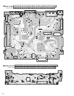
Main section
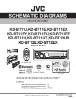
Summary of Contents for KD-BT11E
Page 29: ... No MA387 Rev 003 1 29 ...
Page 66: ... M E M O ...


