


(No.MA387<Rev.003>)1-9
SECTION 2
SPECIFIC SERVICE INSTRUCTIONS
This service manual does not describe SPECIFIC SERVICE INSTRUCTIONS.
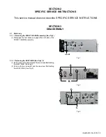
SECTION 3
DISASSEMBLY
3.1
Main body
3.1.1
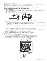
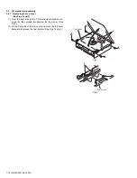
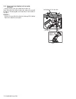
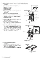
Removing the FRONT CHASSIS assembly (See Fig.1)
(1) Disengage the four hooks
a
engaged the both side of the
FRONT CHASSIS assembly.
Fig.1
3.1.2
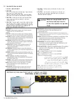
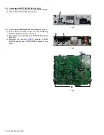
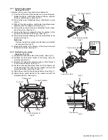
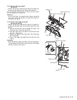
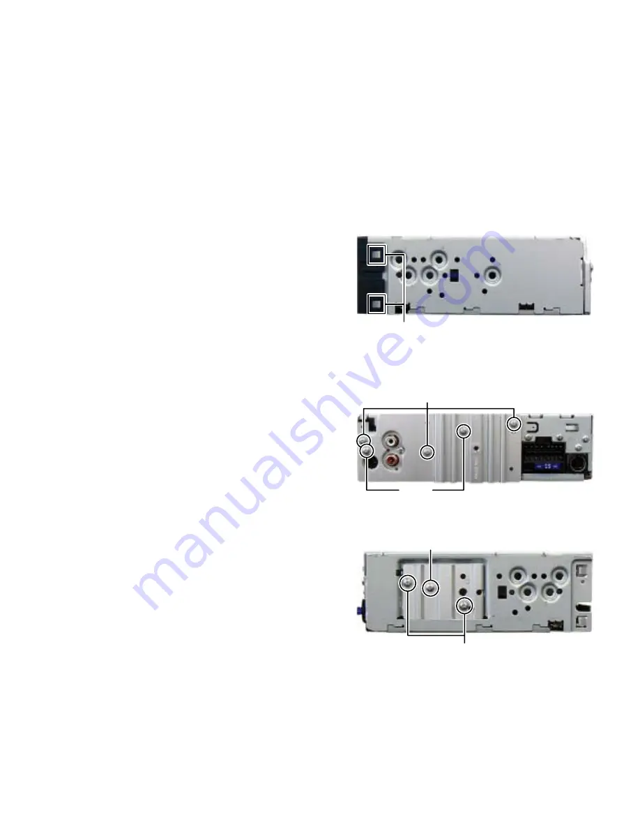
Removing the HEAT SINK (See Fig.2, 3)
(1) Remove the three screws
A
and the two screws
B
attaching
the HEAT SINK. (See Fig.2)
(2) Remove the two screws
C
and the one screw
D
attaching
the HEAT SINK. (See Fig.3)
Fig.2
Fig.3
hook
a
A
B
C
D
Summary of Contents for KD-BT11E
Page 29: ... No MA387 Rev 003 1 29 ...
Page 66: ... M E M O ...


