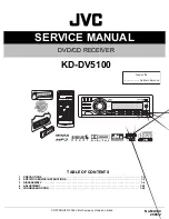


SERVICE MANUAL
COPYRIGHT © 2005 Victor Company of Japan, Limited
No.MA149
2005/2
DVD/CD RECEIVER
MA149
2005
2
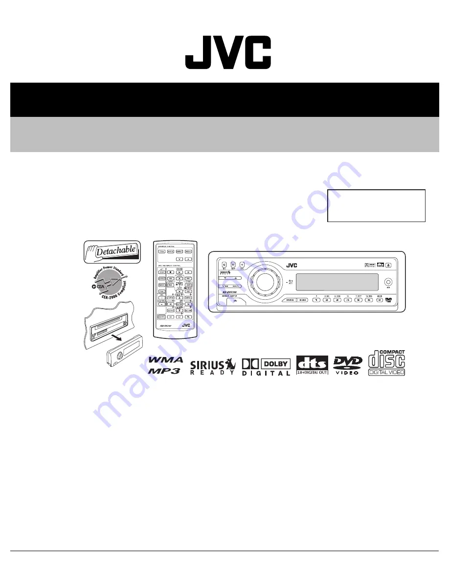
KD-DV5100
TABLE OF CONTENTS
1
PRECAUTIONS . . . . . . . . . . . . . . . . . . . . . . . . . . . . . . . . . . . . . . . . . . . . . . . . . . . . . . . . . . . . . . . . . . . . . . . 1-3
2
SPECIFIC SERVICE INSTRUCTIONS . . . . . . . . . . . . . . . . . . . . . . . . . . . . . . . . . . . . . . . . . . . . . . . . . . . . . . 1-5
3
DISASSEMBLY . . . . . . . . . . . . . . . . . . . . . . . . . . . . . . . . . . . . . . . . . . . . . . . . . . . . . . . . . . . . . . . . . . . . . . . 1-6
4
ADJUSTMENT . . . . . . . . . . . . . . . . . . . . . . . . . . . . . . . . . . . . . . . . . . . . . . . . . . . . . . . . . . . . . . . . . . . . . . . 1-20
5
TROUBLESHOOTING . . . . . . . . . . . . . . . . . . . . . . . . . . . . . . . . . . . . . . . . . . . . . . . . . . . . . . . . . . . . . . . . . 1-28
Area suffix
J --------------- Northern America
Summary of Contents for KD-DV5100
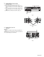
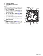
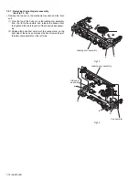
Page 14: ...1 14 No MA149 Fig 8 Fig 9 Clamper unit Clamper spring Notch g Clamper unit ...
Page 29: ... No MA149 1 29 ...
Page 50: ... M E M O ...
Page 64: ... M E M O ...


