
(No.MA287)1-7
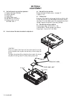
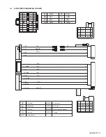
SECTION 3
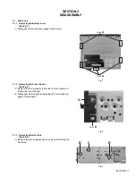
DISASSEMBLY
3.1
Main body
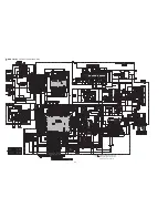
3.1.1 Removing the Bottom cover
(See Fig.1)
(1) Disengage the five hooks
a
engaged bottom cover.
Fig.1
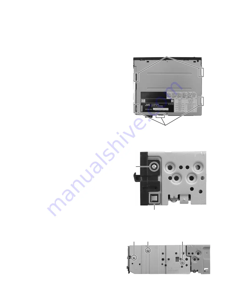
3.1.2 Removing the Front chassis
(See Fig.2)
(1) Remove the two screws
A
(both side of Front chassis) at-
taching the Front chassis.
(2) Disengage the two hooks
b
(both side of Front chassis) en-
gaged Front chassis.
Fig.2
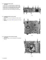
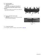
3.1.3 Removing the Heat sink
(See Fig.3)
(1) Remove the two screws
B
and one screw
C
attaching the
Heat sink.
Fig.3
Hook
a
Hook
a
A
Hook
b
B
B
C
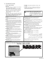
Summary of Contents for KD-G331E
Page 25: ... M E M O ...
Page 56: ... M E M O ...


