1-8 (No.MA287)
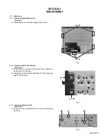
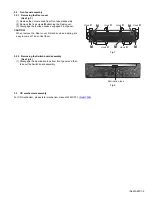
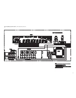
3.1.4 Removing the Rear bracket
(See Fig.4)
(1) Remove the one screw
D
attaching the Remote cable.
(2) Remove the one screw
E
attaching the LINE OUT jack.
(3) Remove the two screws
F
attaching the Connector jack.
(4) Remove the one screw
G
attaching the Antenna jack.
(5) Remove the one screw
H
attaching the IC bracket.
(6) Remove the three screws
J
attaching the Rear bracket.
Fig.4
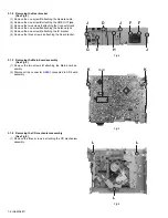
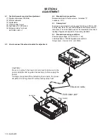
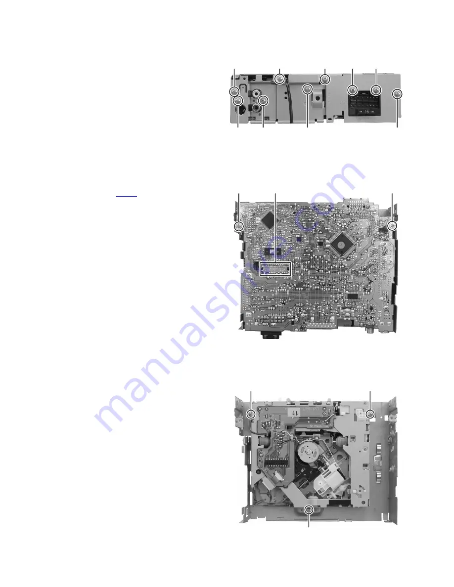
3.1.5 Removing the Main board assembly
(See Fig.5)
(1) Remove the two screws
K
attaching the Main board as-
sembly.
(2) Disconnect the connector
CN501
connected to CD board
assembly.
Fig.5
3.1.6 Removing the CD mechanism assembly
(See Fig.6)
(1) Remove the three screws
L
attaching the CD mechanism
assembly.
Fig.6
D
J
J
F
F
E
H
J
G
K
K
CN501
L
L
L
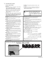
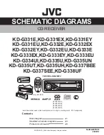
Summary of Contents for KD-G331E
Page 25: ... M E M O ...
Page 56: ... M E M O ...


