1-24 (No.MA178)
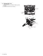
3.2.18 Removing the turn table / spindle motor
(See Figs.41 and 42)
• Prior to performing the following procedure, remove the top
cover, connector board, chassis unit and clamper assembly.
(1) Remove the two screws
L
attaching the spindle motor as-
sembly through the slot of the turn table on top of the body.
(2) Unsolder the wire on the connector board if necessary.
Fig.41
Fig.42
L
Turn table
L
Turn table
Spindle motor
Summary of Contents for KD-G413
Page 45: ... M E M O ...
Page 61: ...XXXXX 3 15 MEMO ...


