KD-LX10/KD-LX30
2-24
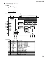
UPD784215GC-165 (IC701) : CPU
1. Pin layout
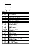
2. Pin function (1/2)
26 ~ 50
1
25
75
51
100 ~ 25
~
~
1
2
3
4
5
6
7
8
9
10
11
12
13
14
15
16
17
18
19
20
21
22
23
24
25
26
27
28
29
30
31
32
33
34
35
36
37
38
39
40
CD mechanism detect switch
CD mechanism detect switch
CD mechanism detect switch
Reset signal input terminal from CD mechanism
Loading motor control signal input terminal
Loading motor control signal input terminal
DIMMER signal output terminal
Non connect
Power supply terminal
Connect to system main clock X'tal osc
Connect to system main clock X'tal osc
Connect to ground
Connect to system sub clock X'tal osc
Connect to system sub clock X'tal osc
System reset signal input terminal
CD mechanism detect switch
J-BUS signal cut in input terminal
Power save 2
CRUISE signal input terminal
Non connect
Non connect
Remote control signal input terminal
Power supply terminal
Power supply terminal
Connect to ground
Connect to ground
Key control 0 input terminal
Key control 1 input terminal
Key control 2 input terminal
Level meter signal input terminal
Non connect
S. meter level input terminal
Connect to ground
Woofer volume signal output terminal(only KD-LX30)
Dot contrast signal output terminal
Power supply terminal
J-BUS data I/O terminal
J-BUS data out put terminal
J-BUS serial clock signal I/O terminal
Initial setting (L)
I
I
I
I
O
O
O
-
-
O
I
-
O
I
I
I
I
I
I
-
-
I
-
-
-
-
I
I
I
I
-
I
-
O
O
-
I/O
O
I/O
I
SW2
SW3
SW4
REST-SW
LM0
LM1
DIMMER-OUT
LCD-PWR
VDD
X2
X1
VSS
XT2
XT1
RESET
SW1
BUS-INT
PS2
CRUISE
NC
NC
REMOCON-IN
AVDD
AVREF0
SBAD IN
NC
KEY0
KEY1
KEY2
LEVEL
NC
S.METER
AVSS
W-VOL
DOT CONT
AVREF
BUS-SI/SO
BUS-SO
BUS-SCK
STAGE 2
Pin
No.
Symbol
Function
I/O


