KD-LX10/KD-LX30
2-25
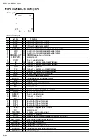
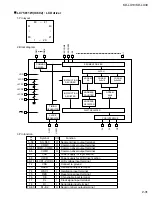
2. Pin function (2/2)
41
42
43
44
45
46
47
48
49
50
51
52
53
54
55
56
57
58
59
60
61
62
63
64
65
66
67
68
69
70
71
72
73
74
75
76
77
78
79
80
81
82
83
84
85
86
87
88
89
90
91
92
93
94
95
96
97
98
99
100
Data output terminal for LCD driver
Clock output terminal for LCD driver
Chip enable 1 output terminal for LCD driver
BUZZER control signal output terminal
Data input terminal from EEPROM
Data output terminal for EEPROM
Clock signal I/O terminal with EEPROM
J-BUS I/O signal terminal
Tray motor negative signal output terminal
Tray motor positive signal output terminal
Door motor negative signal output terminal
Door motor positive signal output terminal
Station detect/Stereo signal input terminal
Local ON/OFF select signal output terminal
Monaural ON/OFF select signal output terminal
DOOR/TRAY open close detect switch signal input terminal
DOOR/TRAY open close detect switch signal input terminal
DOOR/TRAY open close detect switch signal input terminal
DOOR/TRAY open close detect switch signal input terminal
DOOR/TRAY open close detect switch signal input terminal
Non connect
Non connect
AUTO SEEK/STOP select signal output terminal
Non connect
FM/AM select signal output terminal
Chip enable signal output terminal
Data output terminal
Clock signal output terminal
Data input terminal
Non connect
Amp. cut off signal output terminal
Connect to ground
DIMMER signal input terminal
Power save 1
Power ON/OFF select signal output terminal
Power supply control terminal for CD
Mute signal output terminal
Non connect
Non connect
Non connect
Power supply terminal
Data output terminal
Clock signal output terminal
Non connect
Non connect
LCD reset signal output terminal
Chip enable 2 output terminal for LCD driver
Motor speed control signal output terminal
Tray motor control signal output terminal
Initial setting H:KD-LX30J L:KD-LX10J
Micro computer interface clock signal output terminal
Chip enable signal output terminal for micro computer interface
Reset signal input terminal
Test terminal
Micro computer interface data I/O terminal
Micro computer interface data I/O terminal
Micro computer interface data I/O terminal
Micro computer interface data I/O terminal
Initial setting (H:8cm disc uncorrespondence)
Initial setting (H:Non corespondence)
O
O
O
O
I
O
I/O
I/O
O
O
O
O
I
O
O
I
I
I
I
I
-
-
O
-
O
O
O
O
I
-
O
-
I
I
O
O
O
-
-
-
-
O
O
-
-
O
O
O
O
I
O
O
O
-
I/O
]I/O
I/O
I/O
I
I
LCD-DA
LCD-CL
LCD-CE1
BUZZER
E2PR-DA-I
E2PR-DA-O
E2PR-CLK
BUS-I/O
TM0
TM1
DM0
DM1
SD/ST
LOCAL
MONO
CA-SW1
CA-SW2
CA-SW3
CA-SW4
CA-SW5
NC
NC
SEEK/STOP
NC
FM/AM
PLL-CE
PLL-DA
PLL-CK
PLL-DI
NC
AMP KILL
VSS
DIMMER-IN
PS1
POWER
CD-ON
MUTE
W-LPF1
W-LPF2
W-MUTE
VDD
VOL-DATA
VOL-CLK
NC
NC
LCD RST
LCD-CE2
DMK
TMK
STAGE1
BUCK
CCE
RST
TEST
BUS0
BUS1
BUS2
BUS3
DISC SEL(8cmCD)
VOICE IN
Pin
No.
Symbol
Function
I/O


