KD-LX10/KD-LX30
2-36
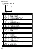
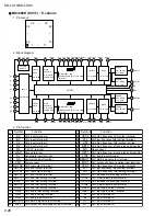
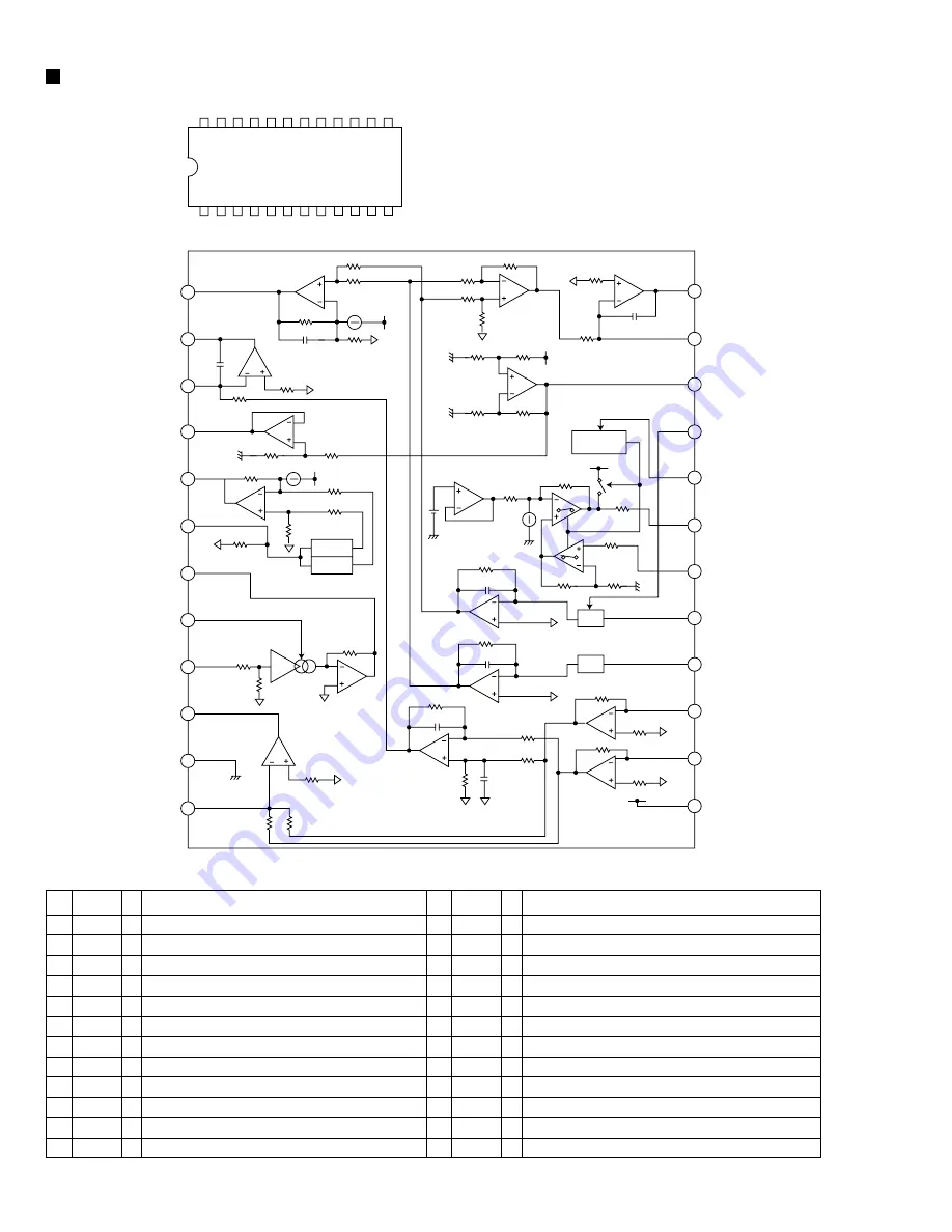
TA2109F-X (IC501) : RF amp.
1. Pin layout
2. Block diagram
3. Pin function
Pin function
24
13
1
12
1
2
3
4
5
6
7
8
9
10
11
12
-
I
I
I
I
I
O
I
I
O
I
O
Power supply input terminal
Main beam I-V amp input terminal
Main beam I-V amp input terminal
Sub beam I-v input terminal
Sub beam I-V input terminal
Monitor photo diode amp input terminal
Laser diode amp output terminal
Laser diode control signal input terminal
T. error balance adj. signal input terminal
Reference voltage output terminal
TE amp negative input terminal
TE error signal output terminal
Vcc
FNI
FPI
TPI
TNI
MDI
LDO
SEL
TEB
2VRO
TEN
TEO
12
11
10
9
8
7
6
5
4
3
2
1
13
14
15
16
17
18
19
20
21
22
23
24
SBAD
FEO
FEN
VRO
RFRP
RFIS
RFGO
RFGC
AGCI
RFO
GND
RFN
3.3k ohm
3.3k ohm
1.53k ohm
re=130 ohm
23.5k ohm
12k ohm
60k ohm
60k ohm
20k ohm
20k ohm
20k ohm
20k ohm
13k ohm
680 ohm
2.12k ohm
BOTTOM
PEAK
20k ohm
20k ohm
20k ohm
12k ohm
1.74k ohm
47k ohm
12k ohm
180k ohm
50uA
21k ohm
21k ohm
7.96k ohm
10k ohm
10k ohm
10k ohm
10k ohm
10pF
36pF
50k ohm
15k ohm
30k ohm
7.67k ohm
10k ohm
30k ohm
15k ohm
20uA
21k ohm 29k ohm
24k ohm 24k ohm
65uA
20pF
180k ohm
20pF
180k ohm
180k ohm
40pF
40pF
I-I
I-I
SW3
SW2
SW1
1k ohm
LCD
3 STATE
DET.
20pF
TEO
TEN
TEB
SEL
LDO
MDI
TNI
TPI
FPI
FNI
Vcc
2VRO
Pin
No.
Symbol I/O
Pin function
13
14
15
16
17
18
19
20
21
22
23
24
O
O
I
O
O
I
O
I
I
O
-
I
Sub beam adder signal output terminal
Focus error signal output terminal
FE amp negative input terminal
Reference voltage (VREF) output terminal
Track count signal output terminal
RFRP detect circuit input terminal
RF gain signal output terminal
RF amplitude adj. control signal input terminal
RF signal amplitude adj. amp input terminal
RF signal output terminal
Ground terminal
RF amp negative input terminal
SBAD
FEO
FEN
VRO
RFRP
RFIS
RFGO
RFGC
AGCI
RFO
GND
RFN
Pin
No.
Symbol I/O


