4 – EN
INSTALLATION / CONNECTION
PREPARATION
This unit is designed to operate on
12 V DC, NEGATIVE ground electrical
systems
. If your vehicle does not have this system, a voltage inverter is required,
which can be purchased at JVC IN-CAR ENTERTAINMENT dealers.
WARNINGS
To prevent short circuits, we recommend that you disconnect the battery’s negative terminal and make all electrical
connections before installing the unit.
•
Be sure to ground this unit to the car’s chassis again after installation.
Notes:
• Replace the fuse with one of the specified rating. If the fuse blows frequently, consult your JVC IN-CAR ENTERTAINMENT
dealer.
• It is recommended to connect to the speakers with maximum power of more than 45 W (both at the rear and at the front,
with an impedance of
4
Ω
to 8
Ω). If the maximum power is less than 45 W, change “AMP GAIN” setting to prevent the
speakers from being damaged (see “General settings—PSM”).
• To prevent short-circuit, cover the terminals of the UNUSED leads with insulating tape.
• The heat sink becomes very hot after use. Be careful not to touch it when removing this
unit.
Heat sink
TROUBLESHOOTING
•
The fuse blows.
* Are the red and black leads connected correctly?
•
Power cannot be turned on.
* Is the yellow lead connected?
•
No sound from the speakers.
* Is the speaker output lead short-circuited?
•
Sound is distorted.
* Is the speaker output lead grounded?
* Are the “–” terminals of L and R speakers grounded in common?
•
Noise interfere with sounds.
* Is the rear ground terminal connected to the car’s chassis using shorter and thicker cords?
•
This unit becomes hot.
* Is the speaker output lead grounded?
* Are the “–” terminals of L and R speakers grounded in common?
•
This unit does not work at all.
* Have you reset your unit?
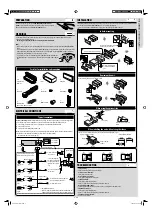
Purple
Front speaker
(left)
To the remote lead of other equipment or
power aerial if any (200 mA max.)
Blue with white
stripe
Red
To an accessory terminal in
the fuse block
To a live terminal in the
fuse block connecting to the
car battery (bypassing the
ignition switch) (constant
12 V)
Yellow *
2
To the metallic body or
chassis of the car
Black
Ignition switch
15 A fuse
Fuse block
Rear speaker
(left)
Rear speaker
(right)
Front speaker
(right)
White with black stripe
Rear ground terminal
Aerial
terminal
Gray with black stripe
Green
Gray
Green with black stripe
Purple with black stripe
White
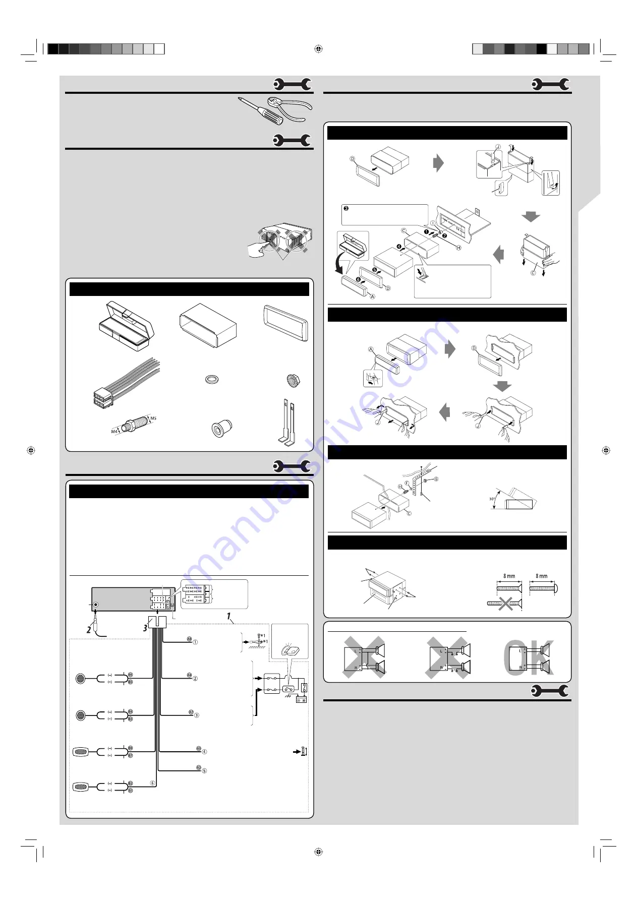
ELECTRICAL CONNECTIONS
Typical connections
Connect only the front speakers if your
speaker system is two-speaker system.
Before connecting:
Check the wiring in the vehicle carefully. Incorrect connection may cause serious damage to this
unit. The leads of the power cord and those of the connector from the car body may be different in color.
1
Connect the colored leads of the power cord in the order specified in the illustration below.
2
Connect the aerial cord.
3
Finally connect the wiring harness to the unit.
Note:
If your vehicle does not have any accessory terminal, move the fuse from the fuse position 1 (initial position) to
fuse position 2, and connect the red lead (A7) to the positive (+) battery terminal.
• The yellow lead (A4) is not used in this case.
Fuse position 2
Fuse position 1
To cellular phone system
Brown
*
1
Not supplied for this unit.
*
2
Before checking the operation of this unit prior to installation, this
lead must be connected, otherwise the power cannot be turned on.
F
Washer (ø5)
C
Sleeve
D
Trim plate
E
Power cord
A
/
B
Control panel/
Hard case
G
Lock nut (M5)
J
Handles
I
Rubber cushion
H
Mounting bolt
(M4 × 5 mm ; M5 × 12.5 mm)
Parts list for installation and connection
INSTALLATION
The following illustration shows a typical installation. If you have any questions or require information regarding installation
kits, consult your JVC IN-CAR ENTERTAINMENT dealer or a company supplying kits.
• If you are not sure how to install this unit correctly, have it installed by a qualified technician.
In dash-mounting
Do the required electrical connections.
Bend the appropriate tabs
to hold the sleeve firmly in
place.
When you stand the unit, be careful not
to damage the fuse on the rear.
Removing the unit
Before removing the unit, release the rear section.
When using the optional stay
Install the unit at an angle of less
than 30˚.
Screw (option)
Stay (option)
Fire wall
Dashboard
When installing the unit without using the sleeve
In a Toyota car for example, first remove the car radio and install the unit in its place.
Flat type screws (M5
× 8 mm)*
Flat type screws (M5 × 8 mm)*
Bracket*
Bracket*
*
Not supplied for this unit.
PRECAUTIONS on power supply and speaker connections
EN_KD-R207[EE]_f.indd 4
EN_KD-R207[EE]_f.indd 4
29/8/08 4:04:19 PM
29/8/08 4:04:19 PM


