background image

3

Before connecting: Check the wiring in the vehicle
carefully. Incorrect connection may cause serious
damage to this unit.
The leads of the power cord and those of the
connector from the car body may be different in color.

1

Connect the colored leads of the power cord to
the car battery, speakers and automatic antenna
(if any) in the following sequence.

1

Black: ground

2

Yellow: to car battery (constant 12 V)

3

Red: to an accessory terminal

4

Blue: to automatic antenna if any (250 mA
max.)

5

Blue with white stripe: to remote lead of other
equipment (200 mA max.)

6

Others: to speakers

2

Connect the antenna cord.

3

Finally connect the wiring harness to the unit.

ENGLISH

‰∑¬


A  

Typical Connections / 

 !"#$

 / 

°“√‡™◊ËÕ¡µËÕ·∫∫ª°µ

 /

 !

 !"#$%&'()*+%,&-.

 !"#$%

 !" #$%!&'(" )*+,-./0


1

 !"#$%&'()*+,-.%/012

 !"#$%&'()*+,-./0123

1

 !"

2

 !"#$%&'()

 12V

3

 !"#$%&'()*+,-

4

 !"#$%&'()*+,-./0

250 mA

5

 !"#$

W


 !"#$%&'(


 200 mA

6

 !"#$%

2

 !" #$%&'

3

 !"#$%&'&()*+,

°ËÕ•∑”°“•‡™•ËÕ¡µËÕ :

 µ•«®†Õ•°“•‡¥‘•†“¬‰ø„•••¬•µÏլ˓ߕ–¡—

¥•–«—լ˓„ÀȺ‘¥æ•“¥„•°“•‡™•ËÕ¡µËÕ™ÿ¥ª•–°Õ•™ÿ¥•’

°“•‡™•ËÕ¡µËÕº‘¥æ•“¥Õ“®∑”„Àȇ°‘¥§«“¡‡†’¬À“¬•È“¬·•ß°—•™ÿ¥ª•–

°Õ••’ȉ¥È †“•µ–°—Ë«¢Õ߆“¬‰ø ·•–¢ÕßÕÿª°••ÏµËÕ‡™•ËÕ¡®“°µ—«•

ß••Õ“®¡’†’∑’ˉ¡Ë‡À¡•Õ•°—•

1

µËÕ “¬µËÕ ’¢Õß “¬‰ø‡¢È“°—∫·∫µ‡µÕ√’Ë√∂¬πµÏ  ”‚æß ·≈–

‡ “Õ“°“»æ“« ‡«Õ√ÏÕ—µ‚π¡—µ‘ (∂È“¡’) µ“¡≈”¥—∫µËÕ‰ªπ’È

1

 ’¥” :  “¬¥‘π

2

 ’‡À≈◊Õß : µËÕ°—∫·∫µ‡µÕ√’Ë√∂¬πµÏ (12 ‚«≈∑ϧß∑’Ë)

3

 ’·¥ß : µËÕ°—∫¢—È« Ë«πª√–°Õ∫

4

 ’øÈ“ : µËÕ‡¢È“°—∫‡ “Õ“°“»Õ—µ‚π¡—µ‘ ∂È“¡’ (¢π“¥ Ÿß ÿ¥

250 mA)

5

 ’πÈ”‡ß‘π≈“¬¢“« :  ”À√—∫ —≠≠“≥√’‚¡µÕÕ° ‡æ◊ËÕµËÕ‡¢È“°—

∫Õÿª°√≥ÏÕ◊Ëπ (¢π“¥ Ÿß ÿ¥ 200 mA)

6

 ’Õ◊Ëπ Ê : µËÕ°—∫≈”‚æß

2

‡™◊ËÕ¡µËÕ°—∫ “¬Õ“°“»

3

 ÿ¥∑È“¬ µËÕ Ë«π§«∫§ÿ¡°“√‡¥‘𠓬‰ø‡¢È“°—∫™ÿ¥ª√–°Õ∫™ÿ¥π’È

ELECTRICAL CONNECTIONS

To prevent short circuits, we recommend that you
disconnect the battery’s negative terminal and make
all electrical connections before installing the unit. If
you are not sure how to install this unit correctly, have
it installed by a qualified technician.

Note:
This unit is designed to operate on 12 V DC, NEGATIVE
ground electrical systems
. If your vehicle does not have
this system, a voltage inverter is required, which can be
purchased at JVC car audio dealers.

• Replace the fuse with one of the specified rating. If

the fuse blows frequently, consult your JVC car
audio dealer.

• If noise is a problem...

This unit incorporates a noise filter in the power
circuit. However, with some vehicles, clicking or
other unwanted noise may occur. If this happens,
connect the unit’s rear ground terminal (see
connection diagram) to the car’s chassis using
shorter and thicker cords, such as copper braiding
or gauge wire. If noise still persists, consult your
JVC car audio dealer.

• Maximum input of the speakers should be more

than 50 W at the rear and 50 W at the front, with an
impedance of 

 to 8 

.

• Be sure to ground this unit to the car’s chassis.
• The heat sink becomes very hot after use. Be

careful not to touch it when removing this unit.

 !

 !"#$%&'()*+,#-./012

 !"#$%&'()*+,-./01+23

 !"#$%&'()*+,-. !/


 !"#$%

 12V

 !"#$%&'

 !

 !"#$%&'()*+,$-%./01)2

 JVC 

 !"#$%&'(

 !"#$%&'()* !+,- !./

 !"

 JVC 

 !"#$%&'

 !"#$

KKK

 !"#$%&'()*+,-./01 23

 !"#$%%&'()*+,-./0123


 !"#$%&

 !"#$%&'(

 !"#$%&'(

 !"

 !"#$

 !"#$%&'()*+,-

 JVC 

 !"

 !"

 !"#$%&'()*+,'-

 50 W 


 – 8 

 !"#$%&'()*+,-

 !"#$%&'(%)*+#,-./#

 !"#$%&'

°“√‡™◊ËÕ¡‚¥¬„™È ‰øøÈ“

‡æ◊ËÕªÈÕß°—π‰øøÈ“≈—¥«ß®√ ‡√“¢Õ·π–π”„Àȧÿ≥‡Õ“¢—È«

≈∫·∫µ‡µÕ√’ËÕÕ°°ËÕπ·≈–∑”°“√‡™◊ËÕ¡‚¥¬„™È‰øøÈ“∑ÿ°®ÿ¥°ËÕπ∑’Ë®–µ‘¥µ—Èß

™ÿ¥ª√–°Õ∫ ∂È“§ÿ≥‰¡Ë·πË„®«Ë“µ‘¥µ—Èß™ÿ¥ª√–°Õ∫π’È∂Ÿ°µÈÕßÀ√◊Õ‰¡Ë

„ÀÈÀ“™Ë“ߺŸÈ‡™’ˬ«™“≠‡ªÁπºŸÈµ‘¥µ—Èß

À¡“¬‡Àµÿ :

™ÿ¥ª√–°Õ∫π’ȉ¥È√—∫°“√ÕÕ°·∫∫¡“‡æ◊ËÕ„™Èß“π°—∫√–∫∫

°√–· ‰øøÈ“ “¬¥‘π¢—È«≈∫°√–· µ√ß 

12 ‚«≈∑Ï

À“°√∂¬πµÏ¢Õߧÿ≥‰¡Ë ‰¥È „™È√–∫∫π’È

µÈÕß„™È‡§√◊ËÕß·ª≈ß°√–· ‰ø™Ë«¬

´÷Ëß “¡“√∂À“´◊ÈÕ‰¥È®“°√È“π¢“¬‡§√◊ËÕ߇ ’¬ß√∂¬πµÏ JVC

„™Èæ‘°—¥®”‡æ“–·∑πø‘« Ï À“°ø‘« Ï¢“¥∫ËÕ¬

„ÀȪ√÷°…“√È“π¢“¬‡§√◊ËÕ߇ ’¬ß√∂¬πµÏ JVC

À“°‡ ’¬ß¡’ª—≠À“...

™ÿ¥ª√–°Õ∫™ÿ¥π’È¡’‡§√◊ËÕß°√Õ߇ ’¬ß„π«ß®√°”≈—ß Õ¬Ë“ß‰√°Á¥’„π√∂¬πµ

∫“ߧ—π°ÁÕ“®‡°‘¥‡ ’¬ß∑’ˉ¡Ëæ÷ߪ√“√∂π“¢÷Èπ‰¥È

À“°ª—≠À“π’ȇ°‘¥¢÷Èπ 

„ÀȵËÕ¢—È« “¬¥‘π¥È“πÀ≈—ߢÕß™ÿ¥ª√–°Õ∫

(¥Ÿ·ºπ¿Ÿ¡‘°“√µËÕ‡™◊ËÕ¡¥È“π) ‡¢È“°—∫

‡™ ´‘ ¢Õß√∂¬πµÏ‚¥¬„™È “¬‡§‡∫‘≈∑’Ë —Èπ·≈–Àπ“°«Ë“ ‡™Ëπ

 “¬‰ø‡§√◊ËÕß«—¥À√◊Õ “¬ª√– “π∑Õß·¥ß ‡ªÁπµÈπ À“°¬—ß

¡’‡ ’¬ßÕ¬ŸËÕ’° „ÀȪ√÷°…“√È“π¢“¬‡§√◊ËÕ߇ ’¬ß√∂¬πµÏ JVC

√–¥—∫Õ‘πæÿ∑∑’Ë¥—ß∑’Ë ÿ¥¢Õß≈”‚æߧ«√¥—߇°‘π°«Ë“ 50 «—µµ ·≈– 50 «—µµÏ

∑—Èß≈”‚æßÀ≈—ß·≈–≈”‚æßÀπÈ“ ‚¥¬¡’Õ‘¡æ’·¥π´Ï„π√–¥—∫ 

4

-

8

µ√«® Õ∫„ÀÈ¥’«Ë“‰¥ÈµËÕ™ÿ¥ª√–°Õ∫™ÿ¥π’È≈ß„π‡™ ´‘ √∂¬πµÏ·≈È«

·ºËπ√–∫“¬§«“¡√ÈÕπ®–√ÈÕπ¡“°À≈—ß®“°„™È √–¡—¥√–«—ßլ˓‰ª

 —¡º— ‡¡◊ËÕ∂Õ¥™ÿ¥ª√–°Õ∫π’È

Heat sink


·ºËπ√–∫“¬§«“¡√ÈÕπ

Antenna terminal

 !

¢—È« “¬Õ“°“»

To antenna

 !

µËÕ°—∫ “¬Õ“°“»

Rear ground terminal

 !"#$%

®ÿ¥‡™◊ËÕ¡µËÕ “¬¥‘π¥È“πÀ≈—ß

*1: Before checking the operation of this unit prior to

installation, this lead must be connected, otherwise
power cannot be turned on.

*1:

 !"#$%&'()*+,-.$/01234

 !"#$%&'()

*1:

°ËÕπ°“√µ√«® Õ∫°“√∑”ß“π¢Õß™ÿ¥ª√–°Õ∫π’È°ËÕπ∑’Ë®–µ‘¥µ—Èß

µÈÕßµËÕ “¬µ–°—Ë«π’È°ËÕπ ¡‘©–π—Èπ®–‰¡Ë “¡“√∂‡ª‘¥‡§√◊ËÕ߉¥È

Line out (see
diagram 

)

 !

 !"


 “¬ÕÕ°

(¥Ÿ·ºπ¿Ÿ¡ 

)

6

1

2

3

4

1

3

*

*

2

5

15

Not included with this unit.

 !"#$


‰¡Ë‰¥È„ÀÈ¡“°—∫™ÿ¥ª√–°Õ∫π

Ignition switch

 !

«‘∑™Ï®ÿ¥√–‡∫‘¥

15 A fuse / 15 A 


=

/

ø‘« Ï¢π“¥ 15A

=

/

White

 ’¢“«

Gray with black stripe

 !"#$

 ’‡∑“·∂∫¥”

Green

 ’‡¢’¬«

Purple

 ’¡Ë«ß

White with black stripe

 !"#$

 ’¢“«·∂∫¥”

Green with black stripe

 !"#$

 ’‡¢’¬«·∂∫¥”

Purple with black stripe

 !"#$

 ’¡Ë«ß·∂∫¥”

Left speaker (front)

 !"#$%

≈”‚æß´È“¬ (ÀπÈ“)

Right speaker (front)

 !"#$%

≈”‚æߢ«“ (ÀπÈ“)

Left speaker (rear)

 !"#$%

≈”‚æß´È“¬ (À≈—ß)

Right speaker (rear)

 !"#$%

≈”‚æߢ«“ (À≈—ß)

Gray

 ’‡∑“

Red

 ’·¥ß

Yellow*

1

*

1

 ’‡À≈◊Õß

*

1

Black

 ’¥”

Blue with white stripe

 !"#$

 ’πÈ”‡ß‘π≈“¬¢“«

Blue

 ’øÈ“

To metallic body or chassis of the car

 !"#$%&'

µËÕ°—∫‚§√ß‚≈À–À√◊Õ‡™ ´‘ ¢Õß√∂¬πµÏ

To a live terminal in the fuse block connecting to the car battery
(bypassing the ignition switch)

 !"#$%&'()*+ !"#$,-./012

 !"#$%&'

µËÕ°—∫¢—È«∑’Ë¡’°√–· ‰øøÈ“„π·ºßø‘« Ï ´÷ËßµËÕ°—∫·∫µ‡µÕ√’Ë√∂¬πµ

(‚¥¬‰¡ËµÈÕß„™È «‘∑™Ï®ÿ¥√–‡∫‘¥)

To automatic 

antenna if any

 !"#$%&'()*

µËÕ‡¢È“°—∫‡ “Õ“°“»Õ—µ‚π¡—µ‘ ∂È“¡’

To an accessory terminal in the fuse block

 !"#$%&'()*

µËÕ°—∫¢—È« Ë«πª√–°Õ∫„π·ºßø‘« 

To remote lead other equipment (see diagram 

)

 !"#$%&'()*+,-./0


F

 ”À√—∫ —≠≠“≥√’‚¡µÕÕ° ‡æ◊ËÕµËÕ‡¢È“°—∫Õÿª°√≥ÏÕ◊Ëπ (¥Ÿ·ºπ¿Ÿ¡‘ 

)

Fuse block

 !"

·ºßø‘« 

wÐdŽ

wÐdŽ

wÐdŽ

wÐdŽ

wÐdŽ

∫qOu²UР¡b³« q³W

∫qOu²UР¡b³« q³W

∫qOu²UР¡b³« q³W

∫qOu²UР¡b³« q³W

∫qOu²UР¡b³« q³W

…—UO9« w „öÝô« WJ³ý s( bQð 

Ê« sJ1 Æ“UN'« qOuð WOKLŽ w QDš Àb×¹ ô v²Š WWbÐ

Æ“UN−K wIOIŠ qDŽ ‰uBŠ v« ¡vÞU)« qOu²« V³9¹

qu*« pKÝË WOzUÐdNJ« WWUD« pKÝ Êu nK²R¹ Ê« sJ1

Æ…—UO9« qJO¼ Êu sŽ

±

±

±

±

±

WOzUÐdNJ« WWUD« b¹Ëeð pK9 W½uK*« „öÝô« qË«

wz«uN«Ë  UŽUL9« ¨…—UO9« W¹—UDÐ l(

ÆwU²« q9K9²« V9Š ©błË Ê«® wJOðU(uðËô«

± 

©…—UO9« qJO¼ l(® ÷—ô« l( ∫œuÝô« pK9«

≤ 

±≤ XÐUŁ®  …—UO9« W¹—UDÐ l( ∫dHô« pK9«

©Xu

≥ 

wU{ô« ·dD« l( ∫dLŠô« pK9«

¥ 

«

9

K

p


«

ô


«

v


«

N

u

«

z

w


«

ô

Ë

ð

u

(

U

ð

O

J

w


«

Ê


Ë

ł

b

©dO³(« wKKO( ≤µ∞ vBWô« b(«®

µ 

pKÝ v« ∫ iOÐôUÐ jD<« ‚—“ô« pK9«

Èdšô«  «bFLK dDO9*«

©dO³(« wKKO( ≤∞∞ vBWô« b(«®

∏ 

 UŽUL9« l( ∫Èdšô« „öÝô«

Æwz«uN« pKÝ qË«

Æ“UN'« l( „öÝô« q(UŠ qË« ¨«dOš«

WOł–uLM«  öOu²«

WOł–uLM«  öOu²«

WOł–uLM«  öOu²«

WOł–uLM«  öOu²«

WOł–uLM«  öOu²«

WOzUÐdNJ«  öOu²«

WOzUÐdNJ«  öOu²«

WOzUÐdNJ«  öOu²«

WOzUÐdNJ«  öOu²«

WOzUÐdNJ«  öOu²«

qBHÐ wu½ ¨WOzUÐdNJ« dz«Ëb« w dOBIð ÀËbŠ lM*

WOzUÐdNJ«  öOu²« qLŽ rŁ VU9« W¹—UD³« ·dÞ

WOHOJÐ p²dF( ÂbŽ WUŠ w Æ“UN'« VOdð q³W

VOdð WOKLŽ „dð vłd¹ ¨`O× qJAÐ “UN'« VOdð

Ác¼ q¦( VOd² q¼R(Ë h²R( hRA “UN'«

Æ…eNłô«

∫WEŠö(

∫WEŠö(

∫WEŠö(

∫WEŠö(

∫WEŠö(

I

b


L

r


¼

c

«


«

'

N

U


O

F

L

q


I

j


Ð

u

«

Ý

D

W


ð

O

U


N

N

N

N

N

d

d

d

d

d

Ð

Ð

Ð

Ð

Ð

U

U

U

U

U

z

z

z

z

z

w

w

w

w

w

(

(

(

(

(

³

³

³

³

³

U

U

U

U

U

ý

ý

ý

ý

ý

d

d

d

d

d


DC

¨

¨

¨

¨

¨


±

±

±

±

±


u

u

u

u

u

X

X

X

X

X

¨

¨

¨

¨

¨


«

«

«

«

«

½

½

½

½

½

E

E

E

E

E

L

L

L

L

L

W

W

W

W

W


N

N

N

N

N

d

d

d

d

d

Ð

Ð

Ð

Ð

Ð

U

U

U

U

U

z

z

z

z

z

O

O

O

O

O

W

W

W

W

W


ð

ð

ð

ð

ð

Q

Q

Q

Q

Q

¹

¹

¹

¹

¹

i

i

i

i

i


Ý

Ý

Ý

Ý

Ý

U

U

U

U

U

V

V

V

V

V

Æ

Æ

Æ

Æ

Æ

w


Š

U

W


Ž

b

Â


Ë

ł

u

œ


(

¦

q


¼

c

«


«

M

E

U

Â


w


Ý

O

U

ð

p

¨


¹

V

«

Ý

²

R

b

«

Â


(

×

u


u

²

U

Ã

¨


Ë

1

J

s


ý

d

«

¡


¼

c

«


«

;

u


(

s


Ë

ö

¡

«

ô

ł

N

e


«

B

u

ð

O

W


K

9

O

U

«


(

U

W


JVC

Æ

«

Ý

²

³

b


«

H

O

u


Ð

P

š

d


¹

×

L

q


½

H

f


«

I

O

U

Ý

U


«

*

u

u

W

Æ

«

«


ð

J

d


«

Š

²

d

«


«

H

O

u

¨


¹

d

ł

v


«

Ý

²

A

U


Ë

ö

¡


«

ô

ł

N

e

«

B

u

ð

O

W


K

9

O

U

«


(

U

W


JVC

Æ

ÆÆÆWKJA*« u¼ ZO−C« ÊU «–«

WWUD« …dz«œ qš«œ ZO−{ d²K “UN'« «c¼ ÂbR²9¹

Ê« sJ1 ¨ «—UO9« iFÐ w ¨p– l( ÆWOzUÐdNJ«

w Æ»užd*« dOž ZO−C« Ë« WIDID« s( Ÿu½ Àb×¹

 i¹—Q²« ·dÞ qË« ¨p– q¦( ÀËbŠ WUŠ

œułu*«

œułu*«

œułu*«

œułu*«

œułu*«

 “UN'« WOHKš w

 “UN'« WOHKš w

 “UN'« WOHKš w

 “UN'« WOHKš w

 “UN'« WOHKš w

qJO¼ l( ©qHÝô« w qOu²« dE½«®

q¦( ¨pLÝ«Ë dBW« „öÝ« «bR²Ý« WDÝ«uÐ …—UO9«

ÂbŽ WUŠ w ÆwÝUOI( pKÝ Ë« ‰Ëb:« ”U×M« pKÝ

¡öË …—UA²Ý« vłd¹ ¨ZO−C« Ë« WIDID« nWuð

 W—U(  «—UO9K WOðuB« …eNłô«

JVC

Æ

vBWô«  UŽUL9«  u qšœ ÊuJ¹ Ê« V−¹

l( ¨ÂU(ô«Ë nK)« s( öJ ◊«Ë µ∞ Ë ◊«Ë µ∞ s( d¦«

 WF½U2

ÂË« ∏ v« ÂË« ¥

ÂË« ∏ v« ÂË« ¥

ÂË« ∏ v« ÂË« ¥

ÂË« ∏ v« ÂË« ¥

ÂË« ∏ v« ÂË« ¥

Æ

Æ…—UO9« qJO¼ l( “UN'« i¹—Qð s( bQð

Æ…—UO9« qJO¼ l( “UN'« i¹—Qð s( bQð

Æ…—UO9« qJO¼ l( “UN'« i¹—Qð s( bQð

Æ…—UO9« qJO¼ l( “UN'« i¹—Qð s( bQð

Æ…—UO9« qJO¼ l( “UN'« i¹—Qð s( bQð

bFÐ «bł WMšUÝ …—«d(« iHš W×OH `³Bð

Æ“UN'« Ÿe½ bMŽ UN²9(ö( ÂbŽ s( bQð Æ«bR²Ýô«

…—«d(« iHš W×OH

*

wHK)« i¹—Q²« ·dÞ

j)« Ãdš

 jD<« dE½«®

©

wz«uN« v«

wz«uN« ·dÞ

*

∫±

V−¹ ¨VOd²« q³W “UN'« «c¼ qOGAð h× q³W

ÊËbÐ “UN'« qOGAð sJ1 ô YOŠ ¨pK9« «c¼ qOuð

ÆpK9« qOuð

œuÝ√

*

±

dH√

dLŠ√

‚—“ô«

iOÐôUÐ jDR( ‚—“ pKÝ

dO³(« ±µ “uO

w½bF*« …—UO9« qJO¼ Ë« w½bF*« r9'« v«

Ëe( dOž

Ò

Æ“UN'« «c¼ l( œ

W¹—UD³« l( Wuu*« “uOH« WŽuL−( w w(« ·dD« v«

©‰UF²ýô« ÕU²H0 «—Ëd(®

“uOH« WŽuL−( w wU{ô« ·dD« v«

 jD<« dE½«® Èdšô«  «bFLK dDO9*« pKÝ v«

©

œuÝôUÐ jDR( iOЫ pKÝ

iOÐ√

ÍœU(—

œuÝôUÐ jDR( ÍœU(—

œuÝôUÐ jDR( dCš√

©WO(U(ô«® Èd9O« WŽUL9«

©WO(U(ô«® vMLO« WŽUL9«

dCš«

w½«uł—«

©WOHK)«® Èd9O« WŽUL9«

©WOHK)«® vMLO« WŽUL9«

œuÝôUÐ jDR( w½«uł—«

“uOH« WŽuL−(

‰UF²ýô« ÕU²H(

błË Ê« wJOðU(uðËô« wz«uN« v«

Instal.KD-S795[U].003A.1.p65

23/12/02, 4:12 PM

3

Summary of Contents for KD-S795

Page 1: ...LISH CD RECEIVER KD S795 INSTRUCTIONS π π GET0144 001A U For installation and connections refer to the separate manual 0 ÿ Ÿ ŸË Õ Ë µË ßÀ π µ µ Èß ËÕ µËÕ CD KD S795 ËÕß Ëπ CD KD S795 COMPACT DIGITAL AUDIO ...

Page 2: ...ments or performance of procedures other than those specified herein may result in hazardous radiation exposure BEFORE USE For safety Do not raise the volume level too much as this will block outside sounds making driving dangerous Stop the car before performing any complicated operations Temperature inside the car If you have parked the car for a long time in hot or cold weather wait until the te...

Page 3: ...rack or a particular portion on a CD 13 Selecting CD playback modes 14 Prohibiting CD ejection 14 SOUND ADJUSTMENTS 15 Selecting preset sound modes C EQ custom equalizer 15 Adjusting the sound 16 SELECTING THE LEVEL DISPLAY 17 DETACHING THE CONTROL PANEL 18 TROUBLESHOOTING 19 MAINTENANCE 20 Handling discs 20 SPECIFICATIONS 21 How to use the M MODE button If you press M MODE the unit goes into func...

Page 4: ... pressed together with DISP display button w SEL select button e MO monaural button r Number buttons t RPT repeat button y RND random button u E EQ equalizer button i CD button o down button 10 button Display window EQ equalizer indicator a LOUD loudness indicator s CD in indicator d CD indicator f FM band indicators FM1 FM2 FM3 g AM band indicator h Tuner reception indicators MO monaural ST stere...

Page 5: ... source changes 7 Searches for stations while listening to the radio Fast forwards or reverses the track if pressed and held while listening to a CD Skips to the beginning of the next track or goes back to the beginning of the current or previous tracks if pressed briefly while listening to a CD Remote controller 1 Turns on the unit if pressed when the unit is turned off Turns off the unit if pres...

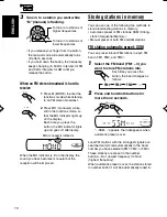
Page 6: ...cause the battery to give off heat crack or start a fire CAUTION DO NOT leave the remote controller in a place such as dashboards exposed to direct sunlight for a long time Otherwise it may be damaged Preparing the remote controller Before using the remote controller Aim the remote controller directly at the remote sensor on the main unit Make sure there is no obstacle in between Do not expose the...

Page 7: ...olume level press the button briefly again If you turn the control dial you can also restore the sound To turn off the power Press and hold for more than one second SEE YOU appears then the unit turns off If you turn off the power while listening to a CD CD play will start from where playback has been stopped previously next time you turn on the power CAUTION on Volume Setting CDs produce very lit...

Page 8: ...CK M minute 2 Adjust the minute 4 Finish the setting To check the current clock time or change the display mode Press DISP display repeatedly Each time you press the button the display mode changes as follows During tuner operation During CD operation During power off The power turns on and the clock time is shown for 5 seconds then the power turns off CLOCK M CLOCK H LEVEL CLOCK M CLOCK H LEVEL C...

Page 9: ...stops To stop searching before a station is received press the same button you have pressed for searching To search stations of lower frequencies To search stations of higher frequencies Selected band appears Lights up when receiving an FM stereo broadcast with sufficient signal strength FM1 FM2 FM3 AM Searching a station manually Manual search 1 Select the band FM1 3 AM Each time you press the bu...

Page 10: ...on stored in number button 1 will be automatically tuned in SSM appears then disappears when automatic preset is over FM1 FM2 FM3 AM 3 Tune in to a station you want while M manual is flashing If you release your finger from the button the manual mode will automatically turns off after 5 seconds If you hold down the button the frequency keeps changing in 50 kHz intervals for FM and 9 kHz intervals ...

Page 11: ...for a few seconds Notes A previously preset station is erased when a new station is stored in the same preset number Preset stations are erased when the power supply to the memory circuit is interrupted for example during battery replacement If this occurs preset the stations again Tuning in to a preset station You can easily tune in to a preset station Remember that you must store stations first ...

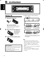
Page 12: ...le driving on such rough roads CD OPERATIONS Elapsed playing time Current track Total track number of the inserted disc Total playing time of the inserted disc CD in indicator All tracks will be played repeatedly until you stop playback Notes When a CD is inserted upside down the CD automatically ejects if the control panel is open If the control panel is closed the source changes to the tuner PLE...

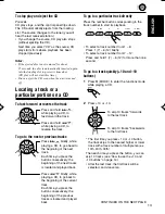
Page 13: ... track number from 7 12 Press and hold 1 7 6 12 for more than one second To go to a track quickly 10 and 10 buttons 1 Press M MODE to enter the functions mode while playing a CD 2 Press 10 or 10 The first time you press 10 or 10 button the track skips to the nearest higher or lower track with a track number of multiple ten ex 10th 20th 30th Then each time you press the button you can skip 10 track...

Page 14: ...d To cancel the prohibition and unlock the CD press and hold again for more than 2 seconds while pressing CD EJECT OK flashes on the display for about 5 seconds and the CD is unlocked How to use the 10 and 10 buttons Ex 1 To select track number 32 while playing track number 6 Ex 2 To select track number 8 while playing track number 36 Selecting CD playback modes To play back tracks at random Disc ...

Page 15: ...qualizer suitable to the music genre Select the sound mode you want When you press the button once the last selected sound mode is recalled and applied to the current source Then each time you press the button the sound modes change as follows Note You can adjust each sound mode to your preference Once you make an adjustment it is automatically stored for the currently selected sound mode See Adju...

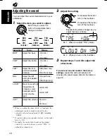
Page 16: ...ble or loudness the adjustment you have made is stored for the currently selected sound mode C EQ including USER 2 If you are using a two speaker system set the fader level to 00 3 Normally the control dial works as the volume control So you do not have to select VOL to adjust the volume level 2 Adjust the setting 3 Repeat steps 1 and 2 to adjust the other items To reset each sound mode to the fac...

Page 17: ...select for more than 2 seconds CLOCK H CLOCK M or LEVEL appears on the display 2 Select LEVEL if not shown on the display 3 Select the desired mode AUDIO 1 Shows the audio level indicator AUDIO 2 Alternates AUDIO 1 setting and illumination display OFF Erases the audio level indicator 4 Finish the setting AUDIO 2 AUDIO 1 OFF Ex When you select AUDIO 2 CLOCK M CLOCK H LEVEL ...

Page 18: ...out of the unit 3 Put the detached control panel into the provided case Attaching the control panel 1 Insert the right side of the control panel into the groove on the panel holder 2 Press the left side of the control panel to fix it to the panel holder Note on cleaning the connectors If you frequently detach the control panel the connectors will deteriorate To minimize this possibility periodical...

Page 19: ...t a CD into the loading slot Insert the CD correctly Causes The volume level is set to the minimum level Connections are incorrect The built in microcomputer may have functioned incorrectly due to noise etc Signals are too weak The antenna is not connected firmly CD is inserted upside down CD R CD RW is not finalized CD is locked You are driving on rough roads CD is scratched Connections are incor...

Page 20: ...ir instructions or cautions carefully Use only finalized CD Rs or CD RWs Some CD Rs or CD RWs may not play back on this unit because of their disc characteristics and for the following reasons Discs are dirty or scratched Moisture condensation on the lens inside the unit The pickup lens inside the unit is dirty CD RWs may require a longer readout time since the reflectance of CD RWs is lower than ...

Page 21: ...f 1 8 µV 75 Ω Alternate Channel Selectivity 400 kHz 65 dB Frequency Response 40 Hz to 15 000 Hz Stereo Separation 35 dB Capture Ratio 1 5 dB AM Tuner Sensitivity 20 µV Selectivity 35 dB CD PLAYER SECTION Type Compact disc player Signal Detection System Non contact optical pickup semiconductor laser Number of channels 2 channels stereo Frequency Response 5 Hz to 20 000 Hz Dynamic Range 96 dB Signal...

Page 22: ...o dealer or a company supplying kits 0103KKSMDTJEIN EN CH TH AR 1 Before mounting Press control panel release button to detach the control panel if already attached When shipped from the factory the control panel is packed in the hard case 2 Remove the trim plate 3 Remove the sleeve after disengaging the sleeve locks 1 Stand the unit Note When you stand the unit be careful not to damage the fuse o...

Page 23: ...slide out the unit Be sure to keep the handles after installing it Parts list for installation and connection The following parts are provided with this unit After checking them please set them correctly 3 2 1 Sleeve ª Õ ÀÿÈ Washer ª Áπ ß À π Fire wall ºπ ß π ø Mounting bolt µ When using the optional stay ËÕ Èµ Õ È Õ ª È ß È È Stay option µ Õ È Lock nut πÕµ ÁÕ Screw option Ÿ Õ È Dashboard ºßÀπÈ ª ...

Page 24: ...Èß µÈÕßµËÕ µ Ë π È ËÕπ π Èπ Ë ª ËÕß È Line out see diagram ÕÕ Ÿ ºπ Ÿ 6 1 2 3 4 1 3 2 5 15 Not included with this unit Ë È ÀÈ ÿ ª Õ π Ignition switch Ï ÿ 15 A fuse 15 A ø Ï π 15A White Gray with black stripe Green Purple Ë ß White with black stripe Green with black stripe Purple with black stripe Ë ß Left speaker front æß È ÀπÈ Right speaker front æß ÀπÈ Left speaker rear æß È À ß Right speaker rea...

Page 25: ...Õ Ë È Õß æß È π È µËÕ ß πµ ª µ À Õ Ë Remote lead µ Ë Rear speakers æßÀ ß Signal cord not supplied with this unit Ë È ÀÈ ÿ ª Õ π È Y connector not supplied with this unit Y ÈÕµËÕ Ÿªµ Y Ë È ÀÈ ÿ ª Õ π È Front speakers æßÀπÈ Blue with white stripe πÈ ß π JVC Amplifier JVC ËÕß ß JVC WOzUÐdNJ WWUD b Ëeð uŠ UNO Mð WOzUÐdNJ WWUD b Ëeð uŠ UNO Mð WOzUÐdNJ WWUD b Ëeð uŠ UNO Mð WOzUÐdNJ WWUD b Ëeð uŠ UNO Mð ...

Reviews: