KD-S795
1-40 (No.49789)
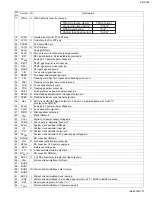
4.10 UPD178078GF-594 (IC701) : System CPU
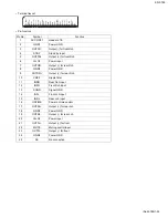
• Pin layout
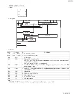
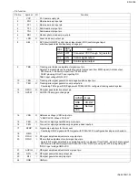
• Pin function
80 ~ 51
1 ~ 30
50
~
31
81
~
100
Pin No.
Symbol
I/O
Function
1~8
NC
-
No use
9
VOL-DA
I/O VOL IC communication line
10
VOL-CLK
O VOL IC communication line
11
NC
-
No use
12
LCD-DA
O LCD driver communication line
13
LCD-CLK
O LCD driver communication line
14,15
NC
-
No use
16
LCD-CE
O LCD driver communication line
17
SW2
I
CD mechanism switch
18
PSW
I
CD mechanism switch
19
LED RED
O Red led lighting control
20
LED BLUE
O Blue led lighting control
21
VOL-1
I
Encoder input
22
VOL-2
I
Encoder input
23
KEY0
I
Key input
24
KEY1
I
Key input
25
KEY2
I
Key input
26
LEVEL
I
Audio level input
27
AVDD
-
Power supply
28
SM
I
Signal level meter input
29
NC
-
No use
30
DOOR SW
I
Door open switch
31
NC
-
No use
32
AVSS
-
Ground
33
REGCPU
-
---
34
VDD
-
Power supply
35
REGOSC
-
---
36
X2
-
System clock
37
X1
I
System clock
38
GND0
-
Ground
39
SD/ST
I
Station detector & Stereo indicator
40
GND2
-
Ground
41
NC
-
No use
42
IFC
I
IF count input
43
VDDPLL
-
Power supply
44
OSC INPUT
I
FM, AM OSC input
45
NC
-
No use
46
GNDPLL
-
Ground
47
AM E.OUT
O PLL error output for AM
Summary of Contents for KD-S795
Page 65: ...KD S795 3 13 M E M O ...

