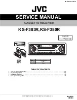
SERVICE MANUAL
COPYRIGHT © 2003 VICTOR COMPANY OF JAPAN, LTD.
No.49813
2003/0
3
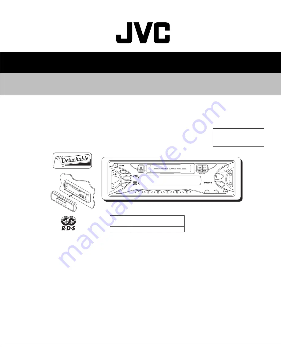
KS-F383R,KS-F380R
CASSETTE RECEIVER
49813
2003
02
KS-F383R,KS-F380R
TABLE OF CONTENTS
1
Important Safety Precautions . . . . . . . . . . . . . . . . . . . . . . . . . . . . . . . . . . . . . . . . . . . . . . . . . . . . . . . . . . . 1-2
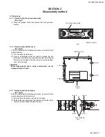
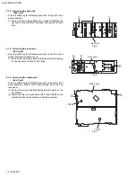
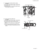
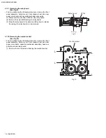
2
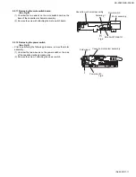
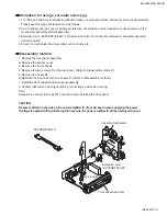
Disassembly method . . . . . . . . . . . . . . . . . . . . . . . . . . . . . . . . . . . . . . . . . . . . . . . . . . . . . . . . . . . . . . . . . . 1-3
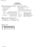
3
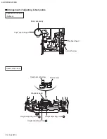
Adjustment method. . . . . . . . . . . . . . . . . . . . . . . . . . . . . . . . . . . . . . . . . . . . . . . . . . . . . . . . . . . . . . . . . . . 1-12
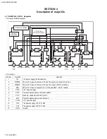
4
Description of major ICs . . . . . . . . . . . . . . . . . . . . . . . . . . . . . . . . . . . . . . . . . . . . . . . . . . . . . . . . . . . . . . . 1-16
Area Suffix
E ---- Continental Europe
EX -------- Central Europe
SEL
LOUD
DISP
SSM
SCM
MO
TP
PTY
AM
FM
Model
KS-F383R
KS-F380R
Illumination color
Amber
Green