background image

SERVICE MANUAL

COPYRIGHT © 2005 Victor Company of Japan, Limited

No.MA220

2005/9

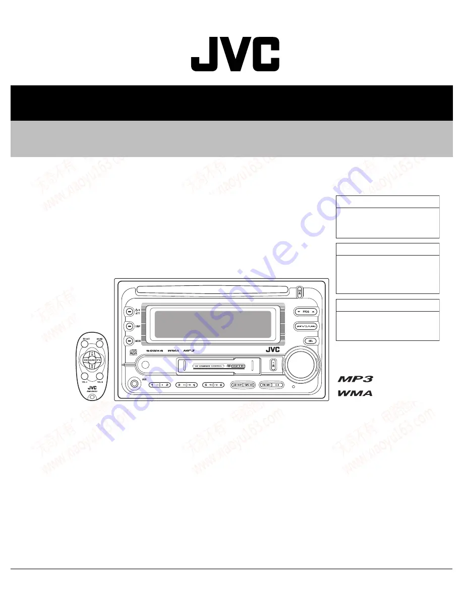
CD/CASSETTE RECEIVER

MA220

2005

9

KW-XC404,KW-XC405,KW-XC406

Lead free solder used in the board (material : Sn-Ag-Cu, melting point : 219 Centigrade)

TABLE OF CONTENTS

1

PRECAUTIONS  . . . . . . . . . . . . . . . . . . . . . . . . . . . . . . . . . . . . . . . . . . . . . . . . . . . . . . . . . . . . . . . . . . . . . . .  1-3

2

SPECIFIC SERVICE INSTRUCTIONS . . . . . . . . . . . . . . . . . . . . . . . . . . . . . . . . . . . . . . . . . . . . . . . . . . . . . .  1-6

3

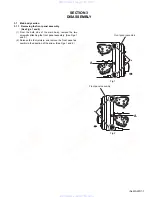
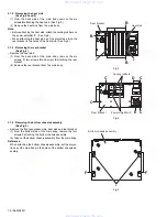
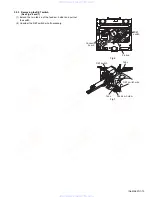
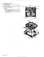
DISASSEMBLY  . . . . . . . . . . . . . . . . . . . . . . . . . . . . . . . . . . . . . . . . . . . . . . . . . . . . . . . . . . . . . . . . . . . . . . .  1-7

4

ADJUSTMENT . . . . . . . . . . . . . . . . . . . . . . . . . . . . . . . . . . . . . . . . . . . . . . . . . . . . . . . . . . . . . . . . . . . . . . .  1-39

5

TROUBLESHOOTING . . . . . . . . . . . . . . . . . . . . . . . . . . . . . . . . . . . . . . . . . . . . . . . . . . . . . . . . . . . . . . . . .  1-44

Area suffix

UI ---------------------------- India

KW-XC404

Area suffix

UT ------------------------- Taiwan
U -------------------- Other Areas

KW-XC405

Area suffix

U -------------------- Other Areas

KW-XC406

www. xiaoyu163. com

QQ 376315150

9

9

2

8

9

4

2

9

8

TEL 13942296513

9

9

2

8

9

4

2

9

8

0

5

1

5

1

3

6

7

3

Q

Q

TEL  13942296513  QQ  376315150  892498299 

TEL  13942296513  QQ  376315150  892498299 

http://www.xiaoyu163.com

http://www.xiaoyu163.com

Summary of Contents for KW-XC404

Page 1: ...CAUTIONS 1 3 2 SPECIFIC SERVICE INSTRUCTIONS 1 6 3 DISASSEMBLY 1 7 4 ADJUSTMENT 1 39 5 TROUBLESHOOTING 1 44 Area suffix UI India KW XC404 Area suffix UT Taiwan U Other Areas KW XC405 Area suffix U Other Areas KW XC406 www xiaoyu163 com QQ376315150 9 9 2 8 9 4 2 9 8 TEL 13942296513 9 9 2 8 9 4 2 9 8 0 5 1 5 1 3 6 7 3 Q Q TEL 13942296513 QQ 376315150 892498299 TEL 13942296513 QQ 376315150 892498299 ...

Page 2: ... dB Capture Ratio 1 5 dB AM Tuner Sensitivity 20 µV Selectivity 35 dB CD PLAYER SECTION Type Compact disc player Signal Detection System Non contact optical pickup semiconductor laser Number of Channels 2 channels stereo Frequency Response 5 Hz to 20 000 Hz Dynamic Range 96 dB Signal to Noise Ratio 98 dB Wow and Flutter Less than measurable limit MP3 Decoding Format MPEG1 2 Audio Layer 3 Max Bit R...

Page 3: ...case of preforming repair of this system Please use enough caution not to see the beam directly or touch it in case of an adjustment or operation check www xiaoyu163 com QQ376315150 9 9 2 8 9 4 2 9 8 TEL 13942296513 9 9 2 8 9 4 2 9 8 0 5 1 5 1 3 6 7 3 Q Q TEL 13942296513 QQ 376315150 892498299 TEL 13942296513 QQ 376315150 892498299 http www xiaoyu163 com http www xiaoyu163 com ...

Page 4: ...ing the traverse unit optical pickup 1 Do not subject the traverse unit optical pickup to strong shocks as it is a sensitive complex unit 2 Cut off the shorted part of the flexible cable using nippers etc after replacing the optical pickup For specific details refer to the replacement procedure in the text Remove the anti static pin when replacing the traverse unit Be careful not to take too long ...

Page 5: ...ay result in hazardous radiation exposure REPRODUCTION AND POSITION OF LABELS Please use enough caution not to see the beam directly or touch it in case of an adjustment or operation check WARNING LABEL CAUTION Visible and Invisible laser radiation when open and interlock failed or defeated AVOID DIRECT EXPOSURE TO BEAM e VARNING Synlig och osynling laserstrålning när den öppnas och spärren är urk...

Page 6: ...does not describe SPECIFIC SERVICE INSTRUCTIONS www xiaoyu163 com QQ376315150 9 9 2 8 9 4 2 9 8 TEL 13942296513 9 9 2 8 9 4 2 9 8 0 5 1 5 1 3 6 7 3 Q Q TEL 13942296513 QQ 376315150 892498299 TEL 13942296513 QQ 376315150 892498299 http www xiaoyu163 com http www xiaoyu163 com ...

Page 7: ...e Figs 1 and 2 2 Release the four joints a and remove the front panel as sembly in the direction of the arrow See Figs 1 and 2 Fig 1 Fig 2 Front panel assembly a A Front panel assembly a A www xiaoyu163 com QQ376315150 9 9 2 8 9 4 2 9 8 TEL 13942296513 9 9 2 8 9 4 2 9 8 0 5 1 5 1 3 6 7 3 Q Q TEL 13942296513 QQ 376315150 892498299 TEL 13942296513 QQ 376315150 892498299 http www xiaoyu163 com http w...

Page 8: ...racket from the main body Fig 3 Fig 4 3 1 4 Removing the bottom chassis assembly See Fig 5 Remove the front panel assembly heat sink and rear bracket 1 From the bottom side of the main body remove the four screws F attaching the bottom chassis assembly 2 Take out the bottom chassis assembly from the main body Reference When attaching the bottom chassis assembly set the projec tions c of the main b...

Page 9: ...as before Fig 6 3 1 6 Removing the cassette mechanism assembly See Fig 7 Remove the front panel assembly heat sink rear bracket and bottom chassis assembly 1 From the inside of the bottom chassis assembly discon nect the card wire from the connector CN403 on the mech anism board 2 Disconnect the wire from the connector CN402 on the mechanism board 3 Remove the four screws H attaching the cassette ...

Page 10: ...an upward direction Fig 8 3 1 9 Removing the main board See Fig 9 Remove the front panel assembly heat sink rear bracket bot tom chassis assembly and middle chassis assembly 1 From the top side of the middle chassis assembly discon nect the wire from the connector CN323 on the main board 2 Remove the four screws M attaching the main board on the middle chassis 3 Remove the main board from the midd...

Page 11: ...heat sink rear bracket bot tom chassis assembly middle chassis assembly and mecha nism board 1 From the inside of the top chassis assembly remove the three screws P attaching the CD mechanism assembly 2 Take out the CD mechanism assembly from the top chas sis Reference When attaching the CD mechanism assembly set the projec tions h of the top chassis assembly in the holes of the CD mechanism assem...

Page 12: ...fiting the switch board little by little 3 Release the sections j while extending the lower section of the front panel assembly in the direction of the arrow and take out the switch board Fig 12 Q Q Q Front panel assembly Switch board j Volume knob Front panel assembly www xiaoyu163 com QQ376315150 9 9 2 8 9 4 2 9 8 TEL 13942296513 9 9 2 8 9 4 2 9 8 0 5 1 5 1 3 6 7 3 Q Q TEL 13942296513 QQ 3763151...

Page 13: ...de of the top cover and move the top cover backward to release the two joints a Fig 1 Fig 2 A A A Joints a Top cover Joints a Top cover www xiaoyu163 com QQ376315150 9 9 2 8 9 4 2 9 8 TEL 13942296513 9 9 2 8 9 4 2 9 8 0 5 1 5 1 3 6 7 3 Q Q TEL 13942296513 QQ 376315150 892498299 TEL 13942296513 QQ 376315150 892498299 http www xiaoyu163 com http www xiaoyu163 com ...

Page 14: ...the connector board in the direction of the arrow to release the two joints b 5 Unsolder the wires on the connector board if necessary CAUTION Unsolder the short circuit point after reassembling Fig 3 Fig 4 Fig 5 B Connector board Pickup Short circuit point Joints b Wires Pickup Short circuit point Soldering Flexible wire B Flexible wire Connector board Frame www xiaoyu163 com QQ376315150 9 9 2 8 ...

Page 15: ...switch wire if necessary Fig 6 Fig 7 Connector board DET switch Pickup DET switch Tab c Tab c DET switch wire Feed sw holder www xiaoyu163 com QQ376315150 9 9 2 8 9 4 2 9 8 TEL 13942296513 9 9 2 8 9 4 2 9 8 0 5 1 5 1 3 6 7 3 Q Q TEL 13942296513 QQ 376315150 892498299 TEL 13942296513 QQ 376315150 892498299 http www xiaoyu163 com http www xiaoyu163 com ...

Page 16: ...re When reassembling make sure that the three shafts on the underside of the chassis unit are inserted to the dampers certainly Fig 8 Fig 9 Suspension spring L Suspension spring L Suspension spring R Suspension spring R Chassis unit Frame Chassis unit Frame Shafts Shaft Damper Damper Damper www xiaoyu163 com QQ376315150 9 9 2 8 9 4 2 9 8 TEL 13942296513 9 9 2 8 9 4 2 9 8 0 5 1 5 1 3 6 7 3 Q Q TEL ...

Page 17: ...row to release the two joints d Fig 10 Fig 11 Clamper arm spring Chassis rivet assembly Joint d Joint d Clamper assembly Clamper arm spring Clamper assembly Joint d Joint d Chassis rivet assembly www xiaoyu163 com QQ376315150 9 9 2 8 9 4 2 9 8 TEL 13942296513 9 9 2 8 9 4 2 9 8 0 5 1 5 1 3 6 7 3 Q Q TEL 13942296513 QQ 376315150 892498299 TEL 13942296513 QQ 376315150 892498299 http www xiaoyu163 com...

Page 18: ...s rivet assembly 2 Disconnect the wire from the loading feed motor assembly if necessary CAUTION When reassembling connect the wire from the loading feed motor assembly to the flame as shown in Fig 12 Fig 12 Fig 13 Loading feed motor assembly Loading feed motor assembly C www xiaoyu163 com QQ376315150 9 9 2 8 9 4 2 9 8 TEL 13942296513 9 9 2 8 9 4 2 9 8 0 5 1 5 1 3 6 7 3 Q Q TEL 13942296513 QQ 3763...

Page 19: ...ng the joint f of the feed rack to the switch of the feed sw holder correct ly 3 As the feed sw holder is temporarily attached to the pickup unit set to the gear of the joint g and to the bending part of the chassis joint h at a time CAUTION Make sure that the part i on the underside of the feed rack is certainly inserted to the slot j of the change lock lever 4 Reattach the feed sw holder using t...

Page 20: ... top plate assembly See Fig 21 Prior to performing the following procedure remove the top cover connector board chassis unit and clamper assembly 1 Remove the screw H 2 Move the top plate assembly in the direction of the arrow to release the two joints r 3 Unsolder the wire marked s if necessary Fig 21 Joint k Trigger arm Chassis rivet assembly Trigger arm Chassis rivet assembly Part p Part m Part...

Page 21: ...elect lock arm in the direction of the arrow to re lease the two joints v 4 The select lock arm spring comes off the select lock arm at the same time Fig 22 Fig 23 Mode sw Select lock arm Joint t Link plate Joint u s Top plate Top plate Select lock arm Select lock arm spring Select lock arm Link plate Joints v Hook w www xiaoyu163 com QQ376315150 9 9 2 8 9 4 2 9 8 TEL 13942296513 9 9 2 8 9 4 2 9 8...

Page 22: ...s shown in the figure 3 Reattach the mode sw while setting the part t to the first peak of the link plate gear and join the joint u CAUTION When reattaching the mode sw check if the points y and z are correctly fitted and if each part operates properly Fig 24 Fig 25 Fig 26 Select lock arm Hook w Boss x Select lock arm spring Joint v Joint v Link plate Joint t Point z Point y Select lock arm Mode s...

Page 23: ...te to the link plate spring while joining them at joint d 3 Reattach the joint a of the select arm R to the first peak of the link plate while joining the two joints b with the slots Then turn the select arm R as shown in the figure The top plate is joined to the joint c CAUTION When reattaching the select arm R check if the points e and f are correctly fitted and if each part operates prop erly F...

Page 24: ...The roller guide springs on both sides come off at the same time CAUTION When reassembling reattach the left and right roller guide springs to the lock arm rivet assembly before reat taching the lock arm rivet assembly to the chassis rivet assembly Make sure to fit the part k of the roller guide spring inside of the roller guide Refer to Fig 34 Fig 31 Fig 32 Fig 33 Fig 34 Roller guide Roller guide...

Page 25: ...g gear 6 and 7 come off the loading gear brack et 2 Pull out the loading gear 5 Fig 35 Fig 36 K Loading gear bracket Loading gear 6 Loading gear 5 Loading gear 3 K Loading gear bracket Loading gear 6 Loading gear 5 Loading gear 7 www xiaoyu163 com QQ376315150 9 9 2 8 9 4 2 9 8 TEL 13942296513 9 9 2 8 9 4 2 9 8 0 5 1 5 1 3 6 7 3 Q Q TEL 13942296513 QQ 376315150 892498299 TEL 13942296513 QQ 37631515...

Page 26: ... three shafts of the chassis rivet assembly upward See Fig 38 9 Detach the loading gear plate rivet assembly from the shaft of the chassis rivet assembly upward while releasing the joint p See Figs 38 and 40 10 Pull out the loading gear 4 Fig 37 Fig 38 Fig 39 Fig 40 Slot m Slot m Joint n Feed gear Loading plate assembly L side plate Chassis rivet assembly Joint p Loading gear 4 Loading gear 2 Load...

Page 27: ...ching the spindle motor as sembly through the slot of the turn table on top of the body 2 Unsolder the wire on the connector board if necessary Fig 41 Fig 42 L Turn table L Turn table Spindle motor www xiaoyu163 com QQ376315150 9 9 2 8 9 4 2 9 8 TEL 13942296513 9 9 2 8 9 4 2 9 8 0 5 1 5 1 3 6 7 3 Q Q TEL 13942296513 QQ 376315150 892498299 TEL 13942296513 QQ 376315150 892498299 http www xiaoyu163 c...

Page 28: ...main chassis while re leasing each two joint tabs a in the direction of the arrow Fig 2 3 3 2 Removing the load arm See Fig 3 1 Remove the E washer attaching the load arm 2 Move the load arm in the direction of the arrow and release the joint b on the cassette catch Fig 3 Mode gear Cassette guide Tab a Tab a Load arm E washer Joint b www xiaoyu163 com QQ376315150 9 9 2 8 9 4 2 9 8 TEL 13942296513 ...

Page 29: ... side of the cassette hanger assembly to release the joint g and h 5 Pull out the cassette catch from the cassette hanger as sembly Fig 4 Fig 5 Fig 6 Fig 7 Cassette holder assembly Side bracket Joints c Cassette holder assembly Cassette hanger assembly Boss d Boss d Cassette hanger assembly Cassette stabilizer spring Hook f Hook e Cassette hanger assembly Hook h Hook g Cassette holder assembly Cas...

Page 30: ...of the load rack under the side bracket assembly Do not reattach the load rack on the boss k CAUTION After reattaching the side bracket assembly confirm op eration Fig 8 Fig 9 Fig 10 A Side bracket assembly Side bracket assembly Joint i Joint j Joint i Joint j Side bracket assembly Boss k Load rack Boss k Load rack www xiaoyu163 com QQ376315150 9 9 2 8 9 4 2 9 8 TEL 13942296513 9 9 2 8 9 4 2 9 8 0...

Page 31: ... remove from the main chassis 2 Remove the rack link CAUTION When reassembling first reattach the rack link and next fit the boss m and hook n of the slide chassis assembly to the hole of the main chassis and engage the two joints l Fig 11 Fig 12 Fig 13 Fig 14 Polywasher Polywasher Pinch arm F assembly Pinch arm R assembly Polywasher Pinch arm F assembly Compulsion spring Pinch arm R assembly Poly...

Page 32: ...emoving the flywheel assembly F R See Fig 18 and 19 REFERENCE It is not necessary to remove the slide chassis assembly 1 Remove the belt at the bottom 2 Remove the two polywashers on the upper side 3 Pull out each flywheel assembly downward Fig 15 Fig 16 Fig 17 Fig 18 B Slide chassis assembly Head Tape guide B Pinch arm spring Head Head support spring Tape guide Pinch spring arm Slid chassis assem...

Page 33: ...ection of the arrow to release the joint r 3 Unsolder the wires if necessary CAUTION When reattaching confirm operation of the MODE switch and the ST BY switch The mode position be tween EJECT and ST BY is optimum for reattach ing Connect the card wire extending from the reel board to the FFC pad before reattaching the reel board Fig 19 Fig 20 Fig 21 Fig 22 Flywheel assembly F Flywheel assembly R ...

Page 34: ...ints t REFERENCE When reattaching the gear base arm make sure that the boss on the gear base assembly is inside the gear base spring 3 3 14 Removing the FFC pad See Fig 25 and 27 1 Push each joint hook u of the FFC pad and remove toward the bottom Fig 23 Fig 24 Fig 25 Gear base link assembly Gear base arm FFC pad Joint t Joint t Joints s Hook u Hook u Gear base arm Screwdriver Gear base spring FFC...

Page 35: ...e the direction plate in the direction of the arrow and engage the three joint x y and z at a time Refer to Fig 29 3 3 18 Removing the mode rack assembly See Fig 27 and 28 1 Move the mode rack assembly in the direction of the arrow to release the two joints b and the joint c REFERENCE When reattaching set the two b on the bottom of the mode rack assembly into the slots of the main chassis and move...

Page 36: ...eel spindle See Fig 32 1 Draw out the reel driver from the shaft on the main chassis and remove the reel driver spring and the reel spindle re spectively CAUTION The reel driver is damaged when removed Please re place with a new one Fig 30 Fig 31 Fig 32 Gear base assembly Pin d Slot e Slot e Polywasher Reflector gear Take up gear Reel driver spring Reel driver spring Reel driver Reel driver Reel s...

Page 37: ...irm operation of each part be fore reattaching the eject cam plate spring Fig 33 Fig 34 Fig 35 Fig 36 Fig 37 Joint f Load rack Eject cam plate spring Eject cam limiter Side bracket assembly Boss g Joint h Load rack Joint f Joint h Boss g Eject cam limiter Side bracket assembly Joint h Joint h Eject cam plate Side bracket assembly Boss g Joint i Eject cam plate Side bracket assembly Eject cam plate...

Page 38: ...f the wires ex tending from the sub motor asswmbly by attaching them to the side of the sub motor assembly with the wires ex tending from the main motor assembly using a spacer Fig 38 Fig 39 Fig 40 Belt Polywasher Polywasher Mode gear Reduction gear A Main motor assembly D Sub motor assembly E Reduction gear B Polywasher Reduction gear B Reduction gear A E D Main motor assembly Sub motor assembly ...

Page 39: ... volume Fader Center Indication 0 Loudness Dolby NR Sound Cruise Off Volume position is about 2V at speaker output with following conditions Playback the test tape VT721 Measuring conditions Amplifier section Power supply voltage DC14 4V 11V to 16V allowance Load impedance 4Ω 4Ω to 8Ω allowance Line out level Impedance 1 0V 20k load 250 nWb m AM mode 999kHz 62dB INT 400Hz 30 modulation signal on r...

Page 40: ...the front panel assembly 2 Remove the heat sink 3 Remove the rear bracket 4 Remove the bottom chassis assembly and middle chassis assembly 5 Remove the main board 6 Remove the CD mechanism assembly 7 Reattach the heat sink with two screws to the main board Refer to Disassembly method 8 Connect the main board front panel assembly bottom chassis assembly and CD mechanism assembly with the extension ...

Page 41: ...speed adjust Motor assembly Azimuth screw B Reverse Azimuth screw A Forward Playback head Azimuth screw B Reverse www xiaoyu163 com QQ376315150 9 9 2 8 9 4 2 9 8 TEL 13942296513 9 9 2 8 9 4 2 9 8 0 5 1 5 1 3 6 7 3 Q Q TEL 13942296513 QQ 376315150 892498299 TEL 13942296513 QQ 376315150 892498299 http www xiaoyu163 com http www xiaoyu163 com ...

Page 42: ...hould be within 45 3 Engage the reverse mode and adjust the output lev el to max with azimuth adjustment screw C The phase difference should be 45 or more 4 When switching between forward and reverse modes the difference between channels should be within 3dB Between FWD L and R REV L and R 5 When VT721 315Hz is played back the level differ ence between channels should be within 1 5dB 2 Tape speed ...

Page 43: ...er key without SEL UP DOWN 3 ACC to OFF DEL EPROM EEPROM clear CD ERROR CD error history call change by FF button E1 to TOTAL DEL CD CD error history clear MAIN TEMP Templature indication of main board VERSION Micon version indication www xiaoyu163 com QQ376315150 9 9 2 8 9 4 2 9 8 TEL 13942296513 9 9 2 8 9 4 2 9 8 0 5 1 5 1 3 6 7 3 Q Q TEL 13942296513 QQ 376315150 892498299 TEL 13942296513 QQ 376...

Page 44: ... IC621 NO Check the connections of CD8V power supply When the lens is moving Does the S search waveform appear at IC681 pin 13 and pin 14 4V Check the pickup and its connections YES NO Is the voltage input at pin 1 and pin 2 of IC681 YES YES NO Is the voltage output at pin 33 of IC621 NO YES Check IC681 Is the power supply present at pin 10 pin 19 and pin 28 of IC681 NO Check the connections of CD...

Page 45: ...age output at pin 41 of IC621 Check the connections between IC681 and IC621 YES Is the power supply present at pin 10 pin 19 and pin 28 of IC681 Is the voltage input at pin 26 of IC681 YES YES Check IC681 NO Check the connections of CD8V power supply NO When the disc is rotated at first Approx 1 2V Is the tracking error signal output at pin 11 of IC601 Check the circuits in IC601 or the vicinity o...

Page 46: ...and pin 37 of IC151 during playback Normal YES NO YES YES NO Check IC572 and its peripheral circuits NO Check IC151 and its peripheral circuits YES Check the power amplifier IC181 NO Is 9V present at pin 10 of IC901 YES Check the connections between pin 40 of IC151 and pin 10 of IC901 NO Check IC901 and its peripheral circuits www xiaoyu163 com QQ376315150 9 9 2 8 9 4 2 9 8 TEL 13942296513 9 9 2 8...

Page 47: ... ser diode is almost worn out and the laser pickup should be replaced If the semi fixed resistor is adjusted while the pickup is functioning normally the laser pickup may be damaged due to excessive current 5 7 Replacement of laser pickup Is RF output 1 3 0 4Vp p YES NO OK Replace it Turn of the power switch and disconnect the power cord Replace the pickup with a normal one Refer to Removing the p...

Page 48: ...R Orange YL Yellow RR FR FL RL REMOTE ANT ACC ILL GND MEMORY Rear Right Front Right Front Left Rear Left Remote out ACC Line Illuminations Control Ground Memory Backup Battery Auto Antenna MEMORY GND ACC ILL RL RL RR RR FL FL FR FR REMOTE ANT REMOTE OUTPUT ONLY POWER ANTENNA www xiaoyu163 com QQ376315150 9 9 2 8 9 4 2 9 8 TEL 13942296513 9 9 2 8 9 4 2 9 8 0 5 1 5 1 3 6 7 3 Q Q TEL 13942296513 QQ 3...

Page 49: ...iaoyu163 com QQ376315150 9 9 2 8 9 4 2 9 8 TEL 13942296513 9 9 2 8 9 4 2 9 8 0 5 1 5 1 3 6 7 3 Q Q TEL 13942296513 QQ 376315150 892498299 TEL 13942296513 QQ 376315150 892498299 http www xiaoyu163 com http www xiaoyu163 com ...

Page 50: ...y 371 8543 Japan Victor Company of Japan Limited VPT Printed in Japan www xiaoyu163 com QQ376315150 9 9 2 8 9 4 2 9 8 TEL 13942296513 9 9 2 8 9 4 2 9 8 0 5 1 5 1 3 6 7 3 Q Q TEL 13942296513 QQ 376315150 892498299 TEL 13942296513 QQ 376315150 892498299 http www xiaoyu163 com http www xiaoyu163 com ...

Page 51: ...ndia KW XC404 Area suffix UT Taiwan U Other Areas KW XC405 Area suffix U Other Areas KW XC406 Contents Block diagram Standard schematic diagrams Printed circuit boards 2 1 2 2 2 6 to 9 CD ROM No SML200509 www xiaoyu163 com QQ376315150 9 9 2 8 9 4 2 9 8 TEL 13942296513 9 9 2 8 9 4 2 9 8 0 5 1 5 1 3 6 7 3 Q Q TEL 13942296513 QQ 376315150 892498299 TEL 13942296513 QQ 376315150 892498299 http www xiao...

Page 52: ...em Safety precaution Please use enough caution not to see the beam directly or touch it in case of an adjustment or operation check www xiaoyu163 com QQ376315150 9 9 2 8 9 4 2 9 8 TEL 13942296513 9 9 2 8 9 4 2 9 8 0 5 1 5 1 3 6 7 3 Q Q TEL 13942296513 QQ 376315150 892498299 TEL 13942296513 QQ 376315150 892498299 http www xiaoyu163 com http www xiaoyu163 com ...

Page 53: ... REMOCON KEY0 KEY1 KEY2 VOL1 VOL2 REMOTE CN902 CN702 Main amplifier section LCD and user control keys section Cassette mechanism control section CN802 CN803 CN701 LOAD FEED MOTOR SPINDLE MOTOR REST SW SW1 SW2 CN001 Block diagram D811 to D839 LED KEYILL SEG1 to SEG62 COM1 to COM10 SUBMO SUBMO VA VB VE VF MD LD VREF FOCUS FOCUS TRACKING TRACKING LOAD FEED LOAD FEED SPINDLE SPINDLE REST SW1 SW2 IC601...

Page 54: ...0 1 0 0 047 UPD784217AGC340 330 SN74AHC126NS X 22k 100 100 100k 100k 47k 47k 47k 47k 220K 220K CRS03 W CRS03 W 10M 12k CRS03 W 10k 10k 1k 3 3k 2 2k 10K 1k 100 10 1k 1k RT1N441C X RT1N441C X CRS03 W CRS03 W QRE142J 102X 9 1k 220 10 100P 100P 2SA1530A QR X 100P 100P 4 7k 100P 100P 100P 100P 1SS355W X KTD1304 X R2S25400DS E MC2836 X MC2838 X 2 2K KTD1304 X 22K 2 2K 2 2K 2 2K 2 2K 820 820 820 820 180 ...

Page 55: ... 0 1 12k 33k 47 6 3 100k 6 8k 0 01 6 8k TC94A34FG 002 0 6 8k 47k 10k 0 01 1k 24K 4 7 35 4 7 35 RT1N141C X RT1P141C X 8 2K 27K 8 2K 27K 150p 150p 4 7 35 4 7 35 10k 4 7k 4 7k 0 1 0 01 100 6 3 100k 6 8k 3 9k 0 18k 1k RT1N141C X 2SA1365 F X 0 01 47u RT1N141C X BA5830FP X 6 8k 2 2K 12k 1 8k 0 01 2SB1184 QR X 4 7 35 47 16 10 6 3 0 1 47 16 1SS355W X 100 TA2157FN X 0 47k 47u 47k NJM4580V X 47 47 PCM1753 X...

Page 56: ...01F1 06 22 16 100 0 015 68k 47k 47k 0 01 0 1 68 2 2k 22k 22k 100k 100k 330k 100 330 100 0 01 680 1 5M 0 1 0 01 RT1N141C X 47k 47k QGB1004K1 16 2 2K 2SB1322 RS T 47 6 3 0 01 47k 47k 47k 56k 2SC3928A QR X 47K 10k 47K 47K 47K 47u 10K QGF1205C1 10 47k 68 0 01 BD4833FVE W 0 0 015 10 16 100P 100P 100P 100P 100k 100k 100k 100k 100P 180 100P 0 1 100P 100P 180 0 1 QVP0033 333Z QVP0033 333Z 0 1 0 1 18k 22 1...

Page 57: ...0 NSPW310BS BRST 390 390 TO1608BCHC Z X NSPW310BS BRST NSPW310BS BRST 820 470 470 680 820 470 330 330 330 330 330 330 330 330 330 330 330 330 330 330 330 330 330 330 330 330 390 390 390 390 MC2838 X 4 7 6 3 3 3K 3 3K 3 3K NSW0246 001X 470 0 047 SEG26 SEG27 SEG28 SEG29 SEG30 SEG31 SEG32 SEG33 SEG34 SEG35 SEG36 SEG37 SEG38 SEG39 SEG40 SEG41 SEG42 SEG43 SEG44 SEG45 SEG46 SEG47 SEG48 SEG49 SEG50 LCDRE...

Page 58: ...55 R256 R281 R282 R758 R921 R759 R735 R736 L781 L782 C783 L702 L703 D701 D702 D703 D704 D705 R901 R902 R903 R904 R905 R906 R907 R908 R909 R910 R911 R912 R913 R914 R915 R916 R922 R923 R924 R925 R941 R971 R972 R973 R974 R975 R976 R977 R978 R979 R980 D706 D707 TU1 D708 D709 B901 B902 B903 C142 C143 C916 D710 Q923 C923 R926 IC701 R782 R783 R784 R785 R786 R787 R788 R789 R790 D711 D712 D713 D714 D715 D7...

Page 59: ... R805 R806 R807 R808 R809 R810 R811 R812 R813 R814 R815 R816 R817 R818 R819 R820 R821 R822 R823 R824 R825 R826 R827 R828 R829 R830 R831 R832 R833 R834 R835 R836 R837 R838 R839 R840 R841 R842 R843 R844 R845 R846 R847 R848 R849 R850 R851 R852 R853 R854 R855 R856 R857 R858 R859 R860 R871 R872 R873 R874 R875 R876 R877 R878 R879 R880 R881 R882 R883 R884 R885 R886 R887 TH855 Lead free solder used in the...

Page 60: ...Q681 R548 R547 R509 R546 R502 R503 R523 R522 R521 R520 R519 R518 R517 R532 R534 R533 R508 R531 R540 R511 R512 R515 R513 R514 R516 R541 R510 R542 R525 R549 R550 R551 R552 R553 R554 R555 R556 R557 R558 R559 R560 R561 R562 R563 R577 R575 R572 R574 R581 R582 R583 R584 R585 R586 R587 R588 R589 R590 R591 R592 R651 R689 R690 R654 C514 C507 R685 R687 R668 R576 C571 R677 R681 R682 R683 R684 R686 R688 R691 ...

Page 61: ... R436 R437 R438 R439 R440 R441 R442 R443 R444 R445 R446 R447 R448 R449 R450 R451 R452 R454 R455 R456 R457 R458 R461 R462 R463 R464 R465 R466 R467 R468 R469 R470 R471 R491 VR401 VR402 X431 IC402 L431 C409 C414 C419 C423 C426 C427 C431 C433 CN401 CN402 CN403 D402 Q403 VR401 VR402 X431 IC402 Lead free solder used in the board material Sn Ag Cu melting point 219 Centigrade Mechanism control board www ...

Page 62: ...tari machi Maebashi city 371 8543 Japan Victor Company of Japan Limited www xiaoyu163 com QQ376315150 9 9 2 8 9 4 2 9 8 TEL 13942296513 9 9 2 8 9 4 2 9 8 0 5 1 5 1 3 6 7 3 Q Q TEL 13942296513 QQ 376315150 892498299 TEL 13942296513 QQ 376315150 892498299 http www xiaoyu163 com http www xiaoyu163 com ...

Page 63: ...cal parts list Block No 01 05 Packing materials and accessories parts list Block No M3 KW XC404 KW XC405 KW XC406 3 2 3 6 3 8 3 13 3 20 Area suffix UI India KW XC404 Area suffix U Other Areas KW XC406 Area suffix U Other Areas UT Taiwan KW XC405 MA220 www xiaoyu163 com QQ376315150 9 9 2 8 9 4 2 9 8 TEL 13942296513 9 9 2 8 9 4 2 9 8 0 5 1 5 1 3 6 7 3 Q Q TEL 13942296513 QQ 376315150 892498299 TEL 1...

Page 64: ...8 15 10 10 11 6 18 4 9 1 5 62 61 7 33 31 22 30 29 39 40 45 44 50 43 42 50 47 36 37 38 49 49 49 67 8 49 41 32 35 22 48 34 46 www xiaoyu163 com QQ376315150 9 9 2 8 9 4 2 9 8 TEL 13942296513 9 9 2 8 9 4 2 9 8 0 5 1 5 1 3 6 7 3 Q Q TEL 13942296513 QQ 376315150 892498299 TEL 13942296513 QQ 376315150 892498299 http www xiaoyu163 com http www xiaoyu163 com ...

Page 65: ...58 57 59 49 52 26 12 12 26 56 55 26 12 3 23 24 24 24 60 25 25 25 10 25 12 54 53 www xiaoyu163 com QQ376315150 9 9 2 8 9 4 2 9 8 TEL 13942296513 9 9 2 8 9 4 2 9 8 0 5 1 5 1 3 6 7 3 Q Q TEL 13942296513 QQ 376315150 892498299 TEL 13942296513 QQ 376315150 892498299 http www xiaoyu163 com http www xiaoyu163 com ...

Page 66: ...406U 32 GE31769 001A D FUNCTION BTN 404UI 405U 405UT 32 GE31769 002A D FUNCTION BTN 406U 33 GE31778 001A BLOCK BUTTON 404UI 405U 405UT 33 GE31778 002A BLOCK BUTTON 406U 34 GE31779 001A BUTTON CDEJ 404UI 405U 405UT 34 GE31779 002A BUTTON CDEJ 406U 35 GE31780 001A CASS EJECT BTN 404UI 405U 405UT 35 GE31780 002A CASS EJECT BTN 406U 36 GE31781 001A BUTTON GROUP 404UI 405U 405UT 36 GE31781 002A BUTTON ...

Page 67: ...V34651 001A REG BKT 67 GE31774 001A LED HOLDER 68 GE31574 031A UT LABEL 405UT Symbol No Part No Part Name Description Local www xiaoyu163 com QQ376315150 9 9 2 8 9 4 2 9 8 TEL 13942296513 9 9 2 8 9 4 2 9 8 0 5 1 5 1 3 6 7 3 Q Q TEL 13942296513 QQ 376315150 892498299 TEL 13942296513 QQ 376315150 892498299 http www xiaoyu163 com http www xiaoyu163 com ...

Page 68: ...5 1 111 3 3 71 111 93 111 91 92 113 88 89 82 87 20 18 115 90 32 30 38 114 11 85 25 73 111 33 34 74 72 35 26 31 22 36 116 29 112 19 61 24 112 62 21 38 76 95 96 14 97 100 123 81 94 77 75 74 73 84 94 101 100 122 93 75 83 www xiaoyu163 com QQ376315150 9 9 2 8 9 4 2 9 8 TEL 13942296513 9 9 2 8 9 4 2 9 8 0 5 1 5 1 3 6 7 3 Q Q TEL 13942296513 QQ 376315150 892498299 TEL 13942296513 QQ 376315150 892498299 ...

Page 69: ...W 73 30321003T LOAD MOTOR WIRE 74 30321005T MODE SW WIRE 75 30321009T SL WIRE 76 30321011T WIRE HOLDER 77 19501403T WIRE CLUMPER 81 303211301T ROLLER SHAFT AS 82 303211501T L GEAR PLATE RV 83 303211302T LOADING PLATE A 84 303211502T LOCK ARM RV ASS 85 303211303T L F MOTOR ASSY 86 30321101T LOADING GEAR 1 87 30321102T LOADING GEAR 2 88 30321103T LOADING GEAR 3 89 30321104T LOADING GEAR 4 90 3032110...

Page 70: ...24 59 28 17 94 64 34 46 3 39 66 66 38 38 32 5 62 75 93 65 33 16 116 108 106 114 114 113 113 110 111 111 107 107 114 111 109 109 117 The parts without symbol number are not service www xiaoyu163 com QQ376315150 9 9 2 8 9 4 2 9 8 TEL 13942296513 9 9 2 8 9 4 2 9 8 0 5 1 5 1 3 6 7 3 Q Q TEL 13942296513 QQ 376315150 892498299 TEL 13942296513 QQ 376315150 892498299 http www xiaoyu163 com http www xiaoyu...

Page 71: ...9S MODE SW ACTUATR 48 1 0802 2020S FRICTION GEARPL 49 1 0802 2021S FRICTION GEARFF 50 1 0802 2022S CASSETTE CATCH 51 1 0802 2026S FFC PAD 59 1 0802 4001S EJECT CAM PL SP 60 1 0802 4002S TU SPG 61 1 0802 4003S FF SPG 62 1 0802 4004S PINCH ARM SPG 63 1 0802 4005S HOLDER STAB SPG 64 1 0802 4006S HOLDER CUSH SPG 65 1 0802 4007S GEAR BASE SPG 66 1 0802 4008S REEL DRIVER SPG x2 67 1 0802 4013S COMPULSIO...

Page 72: ...art Name Description Local www xiaoyu163 com QQ376315150 9 9 2 8 9 4 2 9 8 TEL 13942296513 9 9 2 8 9 4 2 9 8 0 5 1 5 1 3 6 7 3 Q Q TEL 13942296513 QQ 376315150 892498299 TEL 13942296513 QQ 376315150 892498299 http www xiaoyu163 com http www xiaoyu163 com ...

Page 73: ... 223 MEA 512R CFD 250H 1 2 3 5 6 4 www xiaoyu163 com QQ376315150 9 9 2 8 9 4 2 9 8 TEL 13942296513 9 9 2 8 9 4 2 9 8 0 5 1 5 1 3 6 7 3 Q Q TEL 13942296513 QQ 376315150 892498299 TEL 13942296513 QQ 376315150 892498299 http www xiaoyu163 com http www xiaoyu163 com ...

Page 74: ...1 62 33 35 13 10 42 39 www xiaoyu163 com QQ376315150 9 9 2 8 9 4 2 9 8 TEL 13942296513 9 9 2 8 9 4 2 9 8 0 5 1 5 1 3 6 7 3 Q Q TEL 13942296513 QQ 376315150 892498299 TEL 13942296513 QQ 376315150 892498299 http www xiaoyu163 com http www xiaoyu163 com ...

Page 75: ...ITOR 0 47uF 50V J C183 NDC31HJ 101X C CAPACITOR 100pF 50V J C184 NDC31HJ 101X C CAPACITOR 100pF 50V J C185 NCB31CK 104X C CAPACITOR 0 1uF 16V K C186 NCB31CK 104X C CAPACITOR 0 1uF 16V K C187 NDC31HJ 101X C CAPACITOR 100pF 50V J C188 NDC31HJ 101X C CAPACITOR 100pF 50V J C189 NDC31HJ 101X C CAPACITOR 100pF 50V J C190 NDC31HJ 101X C CAPACITOR 100pF 50V J C191 NCB31HK 223X C CAPACITOR 0 022uF 50V K C1...

Page 76: ...NRSA63J 102X MG RESISTOR 1kΩ 1 16W J R715 NRSA63J 473X MG RESISTOR 47kΩ 1 16W J R716 NRSA63J 102X MG RESISTOR 1kΩ 1 16W J R717 NRSA63J 473X MG RESISTOR 47kΩ 1 16W J R720 NRSA63J 103X MG RESISTOR 10kΩ 1 16W J R721 NRSA63J 332X MG RESISTOR 3 3kΩ 1 16W J R722 NRSA63J 103X MG RESISTOR 10kΩ 1 16W J R723 NRSA63J 332X MG RESISTOR 3 3kΩ 1 16W J R724 NRSA63J 103X MG RESISTOR 10kΩ 1 16W J R725 NRSA63J 332X ...

Page 77: ... DIODE D803 1SS355W X SI DIODE D804 1SS355W X SI DIODE D805 1SS355W X SI DIODE D806 1SS355W X SI DIODE D807 1SS355W X SI DIODE D808 1SS355W X SI DIODE D809 1SS355W X SI DIODE D811 NSPW310BS BRST LED D812 NSPW310BS BRST LED D813 NSPW310BS BRST LED D814 TO1608BCHC Z X LED D815 LNJ308G81 1 3 X LED D816 LNJ308G81 1 3 X LED D817 LNJ308G81 1 3 X LED D818 LNJ308G81 1 3 X LED D819 LNJ308G81 1 3 X LED D820...

Page 78: ... Description Local IC501 TMP91CW12AF5VD9 IC IC502 BR24L01AFV W X IC IC503 SN74AHCT126PW X IC DIGITAL IC504 NJU7241F33 X IC IC571 PCM1753 X IC IC572 NJM4580V X IC IC573 SN74AHCU04PW X IC IC601 TA2157FN X RF AMP IC IC621 TC94A14FA IC IC651 NJU7772F15 X IC IC652 TC94A34FG 002 IC IC681 BA5830FP X IC Q501 RT1P141C X DIGI TRANSISTOR Q502 RT1N141C X DIGI TRANSISTOR Q571 RT1P141C X DIGI TRANSISTOR Q572 RT...

Page 79: ...0 NRSA63J 101X MG RESISTOR 100Ω 1 16W J R521 NRSA63J 101X MG RESISTOR 100Ω 1 16W J R522 NRSA63J 101X MG RESISTOR 100Ω 1 16W J R523 NRSA63J 101X MG RESISTOR 100Ω 1 16W J R525 NRSA63J 104X MG RESISTOR 100kΩ 1 16W J R526 NRSA63J 473X MG RESISTOR 47kΩ 1 16W J R528 NRSA63J 473X MG RESISTOR 47kΩ 1 16W J R530 NRSA63J 473X MG RESISTOR 47kΩ 1 16W J R531 NRSA63J 473X MG RESISTOR 47kΩ 1 16W J R532 NRSA63J 10...

Page 80: ...C404 NDC31HJ 101X C CAPACITOR 100pF 50V J C405 NDC31HJ 101X C CAPACITOR 100pF 50V J C406 NDC31HJ 101X C CAPACITOR 100pF 50V J C407 NDC31HJ 101X C CAPACITOR 100pF 50V J C408 NDC31HJ 101X C CAPACITOR 100pF 50V J C409 QEKJ1CM 226Z E CAPACITOR 22uF 16V M C410 NCB31HK 153X C CAPACITOR 0 015uF 50V K C411 NCB31HK 153X C CAPACITOR 0 015uF 50V K C412 NCB31CK 104X C CAPACITOR 0 1uF 16V K C413 NCB31CK 104X C...

Page 81: ... 1 16W J R467 NRSA63J 103X MG RESISTOR 10kΩ 1 16W J R468 NRSA63J 331X MG RESISTOR 330Ω 1 16W J R469 NRSA63J 223X MG RESISTOR 22kΩ 1 16W J R470 NRSA63J 101X MG RESISTOR 100Ω 1 16W J R471 NRSA63J 334X MG RESISTOR 330kΩ 1 16W J R491 NRSA63J 0R0X MG RESISTOR 0Ω 1 16W J VR401 QVP0033 333Z TRIM RESISTOR 33kΩ VR402 QVP0033 333Z TRIM RESISTOR 33kΩ L431 NQL114K 470X COIL 47uH K CN401 QGB1004K1 16 CONNECTOR...

Page 82: ...A2 A4 A5 A6 A7 KW XC405_U XC406_U KW XC404_UI XC405_UT A14 A13 P1 P4 P3 P3 P3 P6 P2 P5 www xiaoyu163 com QQ376315150 9 9 2 8 9 4 2 9 8 TEL 13942296513 9 9 2 8 9 4 2 9 8 0 5 1 5 1 3 6 7 3 Q Q TEL 13942296513 QQ 376315150 892498299 TEL 13942296513 QQ 376315150 892498299 http www xiaoyu163 com http www xiaoyu163 com ...

Page 83: ...008ZA SCREW M5 x 8mm x8 A 9 QYSSSP5008ZA SCREW M5 x 8mm x8 A 10 QAM0456 002 POWER CORD A 11 RM RK50C REMOCON A 12 BATTERY A 13 LV33728 001A CARTON LABEL A 14 GE31574 031A UT LABEL 405UT KIT SRW 222 SCREW PARTS KIT A8 A9 P 1 GE31980 001A CARTON 404UI P 1 GE31982 001A CARTON 405U 405UT P 1 GE32112 001A CARTON 406U P 2 QPC03004315P POLY BAG 30cm x 43cm P 3 FSPG4002 001 POLY BAG 404UI 405UT P 3 FSPG40...

Reviews: