E18
@ @ @ @ @ @
Connecting the power
2. Before recording (continued)
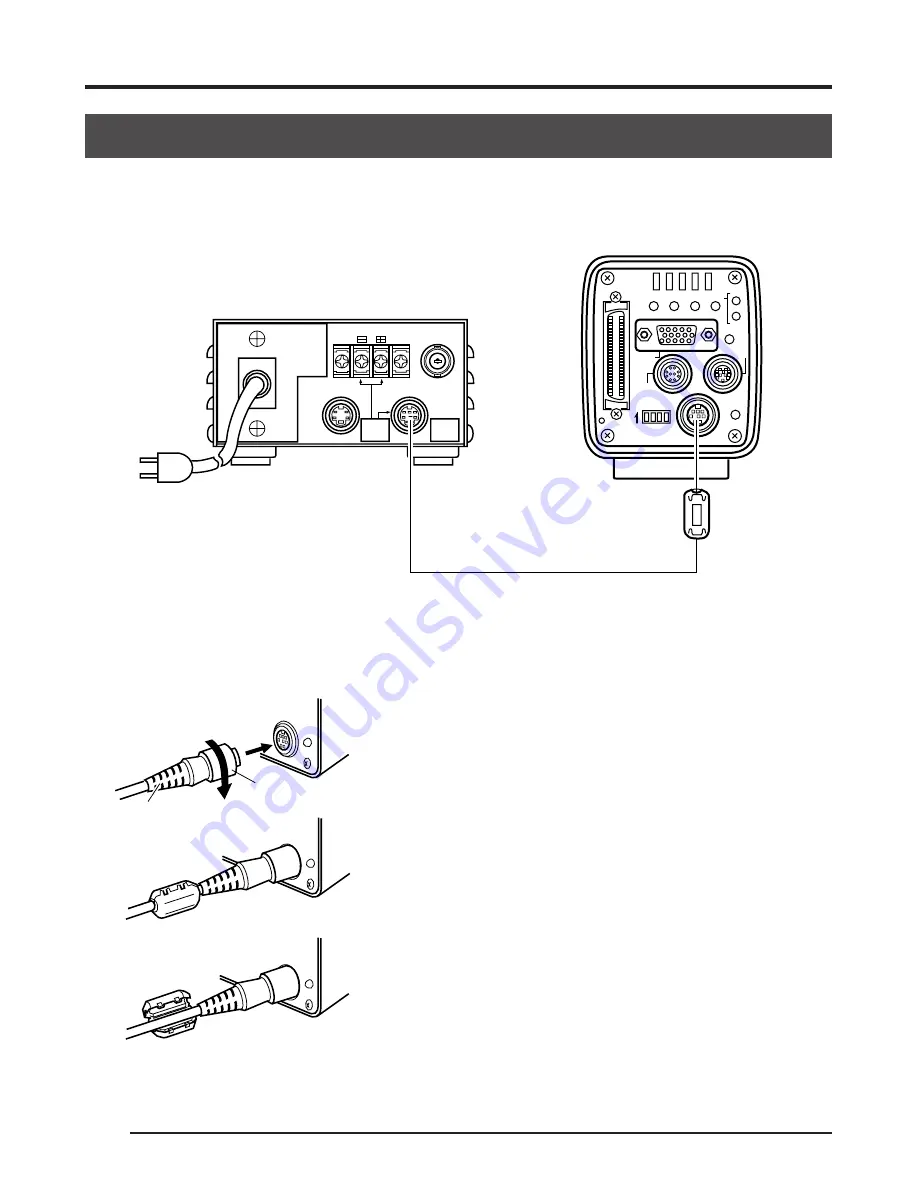
Connect the DC IN terminal on the rear of the main unit and the TO CAMERA terminal of the AC
adapter (AA-P700) with the attached power supply cable (2m).
Before connecting, make sure that the power switch of the AA-P700 is set to OFF. Connecting
with the power turned on may result in malfunction.
VIDEO OUTPUT
TO CAMERA
S(Y/C) OUTPUT
DC 12V=OUTPUT
EITHER
OUTPUT
MAX 1.25A
SEE INST-
RUCTION
MANUAL
AC 100V
AA-P700
AC
SEE INSTRUCTION MANUAL
POWER
DC IN
REMOTE
MONITOR
LENS
FREEZE
PLAY
SET
DOWN
AW/SEL
SEND
SCSI
UP
MENU
MODE
REC
ON 1 2 3 4
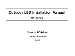
After inserting the plug completely, securely fasten by
turning the ring.
To reduce emission of unwanted electrical waves, mount
the attached ferrite core as shown in the diagram on
the left.
Mount the ferrite core as close to the main unit as pos-
sible as shown in the diagram.
Connect the plug to the AC adapter side in the same
manner.
DC IN
POWER
DC IN
POWER
DC IN
POWER
AC adapter
Attached power supply cable
Clamp filter
Plug
Ring


