background image

11

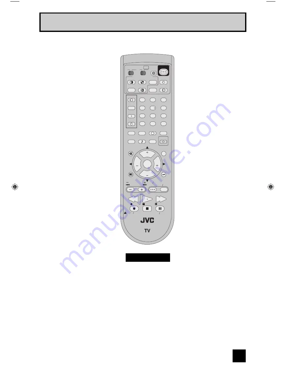
INPUT

INDEX

ASPECT

FREEZE

SWAP

SELECT

FAVORITE

THEATER

PRO

NATURAL

CINEMA

VIDEO

STATUS

TIMER

i.LINK MENU

SOUND

LIGHT

TV CATV VCR DVD

MUTING

MENU

BACK

GUIDE

RM-C14G

REW

VCR CHANNEL

PREV   NEXT

VCR   DVD

POWER

TV   VCR

FF

PLAY

REC

PAUSE

OPEN  CLOSE

STILL  PAUSE

STOP

CH

CH

VOL

VOL

OK

MULTI SCREEN

TWIN

D/A

1

2

3

4

5

6

7

8

9

0

TUNE

TV

POWER

C.C.

SUB

CHANNEL

SUB

ML/MTS

SLEEP

DISPLAY

+

Quick Setup                           TV Remote Control

RM-C14G

Notes:

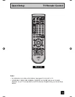
•    For information on remote control buttons, see pages 59 - 69 and 73 - 78.

•   i.LINK MENU, TIMER, SUB CHANNEL, FAVORITE and GUIDE buttons are for digital 

channels.  If your TV is connected to an ATSC antenna or Digital Cable, you can use these 
buttons.

LCT1881-001B-A ENG e   11

5/20/05, 4:29:10 PM

Summary of Contents for LT-40X776/S

Page 1: ...r Company of Japan Limited No YA301 2005 8 LCD FLAT TELEVISION YA301 2005 8 LT 40X776 S TABLE OF CONTENTS 1 PRECAUTION 1 3 2 SPECIFIC SERVICE INSTRUCTIONS 1 6 3 DISASSEMBLY 1 10 4 ADJUSTMENT 1 17 5 TROUBLESHOOTING 1 25 BASIC CHASSIS FL2 ...

Page 2: ...orizontal 1366 dots Vertical 768 dots W XGA Audio Power Output 10 W 10 W Speaker 6 6 cm round type 4 Antenna terminal VHF UHF F type connector 75 Ω unbalanced coaxial Video Audio input INPUT 1 2 3 Component Video INPUT 1 1125i 750p 525p 525i S Video INPUT 1 2 Video Audio RCA pin jack 3 Y 1 V p p Sync signal 0 35V p p 3 value sync 75 Ω Pb Pr 0 35V p p 75 Ω Y 1 V p p Positive Negative sync provided ...

Page 3: ...ts that indicate evidence of overheating should be replaced Always use the manufacturer s replacement components 6 Isolation Check Safety for Electrical Shock Hazard After re assembling the product always perform an isolation check on the exposed metal parts of the cabinet antenna terminals video audio input and output terminals Control knobs metal cabinet screw heads earphone jack control shafts ...

Page 4: ...NSTALLATION REQUIREMENTS To ensure safety in an emergency such as an earthquake and to prevent accidents ensure that measures are taken to prevent the TV dropping or falling over Tie commercially available tough cord s to the hooks in the back of the TV and fix the TV to solid walls or columns 1 2 4 NOTES ON HANDLING 1 WHEN TAKING UNIT OUT OF A PACKING CASE When taking the unit out of a packing ca...

Page 5: ...during transportation and storage as the LCD panel is very vulnerable to lateral impacts and may break During transportation ensure that the unit is loaded along the traveling direction of the vehicle and avoid stacking them on one another For storage ensure that they are stacked in 2 layers or less even when placed upright 1 3 2 OPTICAL FILTER ON THE FRONT OF THE LCD PANEL 1 Avoid placing the uni...

Page 6: ...80i 480p 720p 1080i in Digital in is displayed V CHIP Since the V CHIP is built in it can choose view and listen to a healthy program MTS STEREO The voice multiplex function of the MTS system is built in MTS Multi channel Television Sound system NATURAL CINEMA Watching the movie or animation press the Natural Cinema to adjust the out line of the images to make thin more sharp BBE High definition a...

Page 7: ... or lighting with the brightness twice as brighter as originally lighting For checking this pixel fault input 100 of each R G B colour and find out the cell that is not lighting 3 FLICKER FAULT In the pixel fault a cell that should light originally or not light originally is flashing on and off For checking this pixel fault input ALL BLACK SCREEN signal or 100 of each RGB colour and find out the c...

Page 8: ...d 28 CLK2 O Not used Digital tuner control 78 NC O Not used 29 RxD2 I Not used Digital tuner control 79 NC O Not used 30 TxD2 O Not used Digital tuner control 80 NC O Not used 31 SDA2 I O Not used 81 NC O Not used 32 DIGR1 O R 1 for OSD 82 NC O Not used 33 DIGG1 O G 1 for OSD 83 NC O Not used 34 DIGB1 O B 1 for OSD 84 WAKE O Reset for sub chassis CPU 35 TxD0 I Data receive serial for external prog...

Page 9: ...N01P for Frash ROM type 25 MODE I Single chip mode 75 NMI I 3 3V power supply 26 BS1 5CTL O Not used Digital tuner power reset control 76 COMP I AV COMPULINK lll control 27 A92RES O Reset for IC1001 3D YC SEP COLOR DEMODULAT Reset H 77 REMO I Remote control 28 BS_RST O Not used Reset for Digital tuner power reset control 78 VSYNC I V sync pulse 29 LIP_RST O Not used Reset for Sound delay Lip sync ...

Page 10: ... REAR COVER 1 Remove the 3 screws L then remove the CONTROL ASSY with the FRONT CONTROL PWB 2 Remove the FRONT CONTROL PWB 3 2 7 REMOVING THE RECEIVER PWB Fig 1 Remove the STAND Remove the REAR COVER 1 Remove the 3 screws M and the 1 screw N then remove the TUNER BASE 2 Remove the 2 screws P and the 2 screws Q then remove the TOP SHIELD CASE 3 Remove the 2 screws R then remove the RECEIVER PWB 3 2...

Page 11: ...KET B A B C D E M N V P U Q W X Y F F R S Z B A T L L J G H STAND STAND COVER JACK COVER JACK COVER TUNER BASE COOLING FAN ATSC TUNER MODULE PWB DIGITAL SIGNAL PWB SUB POWER PWB SD CARD PWB CONNECTOR PWB POWER CORD HOLDER ANALOG SIGNAL PWB TERMINAL BASE FRONT CONTROL PWB CONTROL ASSY POWER CORD MAIN POWER PWB REAR COVER REGULATOR PWB RECEIVER PWB K ...

Page 12: ... Remove the FAN BRACKET Remove the SUB POWER PWB BRACKET Remove the FRONT LED PWB 1 Remove the 2 screws M then remove the LED LENS 3 2 17 REMOVING THE CARD PWB Fig 2 Remove the STAND Remove the REAR COVER 1 Remove the 2 screws C then remove the CARD BASE 2 Remove the 1 screw D then remove the CARD PWB BRACKET with CARD PWB 3 Remove the 4 screws E then remove the CARD PWB 3 2 18 REMOVING THE LCD PA...

Page 13: ...No YA301 1 13 Fig 2 BOTTOM FRAME CARD PWB BRACKET CARD PWB SHIELD SUB BRACKET SUB BRACKET TOP FRAME MAIN BASE FRONT F G L L H D A E C A B J K SPEAKER SPEAKER FRONT LED PWB CARD PWB CARD BASE FRONT PANEL ...

Page 14: ...d 5 User setting Check the user setting items according to the given in page later Where these do not agree refer to the OPERATING INSTRUCTIONS and set the items as described 6 SERVICE MODE setting Verify what to set in the SERVICE MODE and set whatever is necessary Fig 1 Refer to the SERVICE ADJUSTMENT for setting 3 3 2 SERVICE MODE SETTING SERVICE MODE SCREEN Fig 1 SETTING ITEM MAIN MENU SCREEN ...

Page 15: ... 00 00 00 00 COLOR 10 00 10 00 TINT 00 00 00 00 DETAIL 05 00 00 00 ENERGY SAVER MODE 30 20 00 10 COLOR TEMPERATURE HIGH LOW HIGH HIGH DIG NOISE CLEAR OFF OFF OFF OFF COLOR MANAGEMENT ON ON ON ON DYNAMIC GAMMA ON ON ON ON SMART PICTURE ON ON ON ON Setting item DYNAMIC STANDARD GAME THEATER PICTURE 00 00 00 00 BRIGHT 00 00 00 00 COLOR 05 00 10 00 TINT 00 00 00 00 DETAIL 05 00 00 00 ENERGY SAVER MODE...

Page 16: ...he tweezers and remove the chip part Transistors diodes variable resistors etc 1 Apply extra solder to each lead 2 As shown in the figure push the part with tweezers and alternately melt the solder at each lead Shift and remove the chip part NOTE After removing the part remove remaining solder from the pattern 2 How to install Chip parts Resistors capacitors etc 1 Apply solder to the pattern as in...

Page 17: ...ustment 1125i A D OFFSET adjustment SUB SCREEN A D OFFSET adjustment WHITE BALANCE HIGHLIGHT adjustment MTS CIRCUIT MTS INPUT LEVEL adjustment MTS SEPARATION adjustment 4 5 BASIC OPERATION OF SERVICE MODE 4 5 1 HOW TO ENTER THE SERVICE MODE 1 Set to 0 minutes using the SLEEP TIMER key 2 Press the VIDEO STATUS key and DISPLAY key simultaneously then enter the SERVICE MODE Fig 1 Fig 1 NOTE Before en...

Page 18: ...TTING ITEM CH CH key Change the setting items up down SLEEP TIMER key Switches to the next items CHANGE OF SETTING VALUE DATA VOL VOL key Change the setting values up down MEMORY OF SETTING VALUE DATA Changed setting value is memorized by pressing MUTING key NTSC3 525i Composite S video input 525I 525i Component input 525P 525p 1125I6 1125i 750P 750p H525I HDMI 525i H525P HDMI 525p H125I6 HDMI 112...

Page 19: ...5 000 S025 Not display 000 255 000 S026 Not display 000 255 000 S027 Not display 000 255 000 S028 Not display 000 255 000 S029 Not display 000 255 000 S030 R DRIVE 000 255 130 S031 G DRIVE 000 255 133 S032 B DRIVE 000 255 090 S033 Not display 000 255 000 S034 Not display 000 255 000 S035 Not display 000 255 000 S036 Not display 000 255 000 S037 Not display 000 255 000 S038 Not display 000 255 000 ...

Page 20: ...tem No Item name Variable range Setting value D063 Not display 00 FF 00 D064 Not display 00 FF 00 D065 Not display 00 FF 00 D066 Not display 00 FF 00 D067 Not display 00 FF 00 D068 Not display 00 FF 00 D069 Not display 00 FF 00 D070 Not display 00 FF 00 D071 Not display 00 FF 00 D072 Not display 00 FF 00 D073 Not display 00 FF 00 D074 Not display 00 FF 00 D075 Not display 00 FF 00 D076 Not display...

Page 21: ...0 FF 00 D152 Not display 00 FF 00 D153 Not display 00 FF 00 D154 Not display 00 FF 00 D155 Not display 00 FF 00 Item No Item name Variable range Setting value D156 Not display 00 FF 00 D157 Not display 00 FF 00 D158 Not display 00 FF 00 D159 Not display 00 FF 00 D160 Not display 00 FF 00 D161 Not display 00 FF 00 D162 Not display 00 FF 00 D163 Not display 00 FF 00 D164 Not display 00 FF 00 D165 No...

Page 22: ...ECT to FULL 4 Set COLOR TEMPERATURE to LOW 5 Select 1 ADJUST from the SERVICE MODE 6 Set S030 R DRIVE S031 G DRIVE and S032 B DRIVE to 133 7 Set S001 adjustment setting mode change to set the values 012 and it change to the 1125i black level adjustment setting mode 8 Adjust S012 1125i brightness to set the 0 black part in the upper half of the screen to be brightest 9 Set S001 to set 000 and it ch...

Page 23: ...7 Sub screen cr offset to minimize the red noise in the upper half of the screen 11 Readjust S016 and S017 to set the upper half of the screen to be the blackest See Fig 9 12 Set S001 to set 000 and it change to the normal mode 13 Press the MUTING key to memoirze the set value WHITE BALANCE HIGHLIGHT Remote control unit Signal generator 1 ADJUST S030 R DRIVE Red drive S031 G DRIVE Green drive S032...

Page 24: ...1 Input the stereo L signal 300Hz from the TV audio multiplex signal generator to the antenna terminal 2 Connect an oscilloscope to L OUT pin of the AUDIO OUT and display one cycle portion of the 300Hz signal 3 Change the connection of the oscilloscope to R OUT pin of the AUDIO OUT and enlarge the voltage axis 4 Select 1 ADJUST from the SERVICE MODE 5 Set the initial setting value of the T002 LOW ...

Page 25: ...by pressing the POWER key on the remote control unit when in the Self check display mode 5 1 4 FAILURE HISTORY Failure history can be counted up to 9 times for each item When the number exceeds 9 display will remain as 9 Failure history will be stored in the memory unless it has been deleted NOTE Only SYNC with without sync signals will be neither counted nor stored 5 1 5 POINTS TO NOTE WHEN USING...

Page 26: ...ply of ACK signal an error will be counted Digital tuner DIG Not used Main memory MEM Confirmation of reply of ACK signal which uses I2C communication IC7602 DIGITAL SIGNAL PWB SDA If it checks whenever I2C communication is performed and no reply of ACK signal an error will be counted AV select switch AVSW Same as above IC301 IC501 ANALOG SIGNAL PWB SDA Same as above 3 dimensions YC separator YC S...

Page 27: ...e in PANEL TMP Not used Abnormal rise of temperature in AUDIO PWB ATP Not used Short circuit detection of AUDIO PWB ASH Not used Panel communication PNL Not used Sub memory MEM Not used Temp sensor TMP Not used Audio control AIO Not used Abnormal rise of CARD VIEWER PWB CARD Comfirmation of reply of ACK signal which uses SDA communication IC1001 CARD VIEWER PWB SDA If it checks whenever SDA commun...

Page 28: ... No YA301 AV MULTIMEDIA COMPANY DISPLAY CATEGORY 12 3 chome Moriya cho Kanagawa ku Yokohama city Kanagawa prefecture 221 8528 Japan Victor Company of Japan Limited VPT Printed in Japan ...

Page 29: ...pacitor MF R Metal Film Resistor MF CAP Metalized Film Capacitor MG R Metal Glazed Resistor MM CAP Metalized Mylar Capacitor MP R Metal Plate Resistor MP CAP Metalized Polystyrol Capacitor OM R Metal Oxide Film Resistor PP CAP Polypropylene Capacitor CMF R Coating Metal Film Resistor PS CAP Polystyrol Capacitor UNF R Non Flammable Resistor TF CAP Thin Film Capacitor CH V R Chip Variable Resistor M...

Page 30: ...M2 3 15 SUB POWER P W BOARD ASS Y SFL 9702A M2 3 16 DIGITAL SIGNAL P W BOARD ASS Y SFL0D134A M2 3 16 RECEIVER P W BOARD ASS Y SFL0F801A M2 3 22 DIGITAL TUNER MODULE P W BOARD ASS Y SSD 2101A M2 3 22 REMOTE CONTROL UNIT PARTS LIST RM C14G 1H 3 23 PACKING PARTS LIST 3 23 PACKING 3 24 USING P W BOARD REMOTE CONTROL UNIT P W B ASS Y name P W B ASS Y No ANALOG SIGNAL P W B SFL 1123A M2 CONNECTOR P W B ...

Page 31: ... 118 QQR0491 001 FERRITE CORE 119 LC33103 001A 0K POWER CORD HOLDER 120 LC21596 006A HK TERMINAL BASE 121 LC33196 003B 0K CONTROL ASSY 122 QUQ105 3004AA E FFC WIRE 30pin 4cm 123 QUQ105 5004AA E FFC WIRE 50pin 4cm 124 QUQ105 4006AL E FFC WIRE 40pin 6cm 125 QUQ105 5013AE E FFC WIRE 50pin 13cm 126 QUQ105 5013AE E FFC WIRE 50pin 13cm 127 QUQK12 2106CH E FFC WIRE 21pin 6cm 128 LC21597 005B HK TUNER BAS...

Page 32: ... DIGITAL BRACKET SHIELD COVER INSULATOR FRONT RECEIVER PWB BRACKET SUB POWER PWB BRACKET 101 107A 110 108 107 133 109 106 128 129 130 207 134 203 121 206 120 127 125 126 131 119 117 118 210 204 122 123 208 124 202 201 112 101 113 114 102 103 111 105 209 104 205 115 132 116 ...

Page 33: ...IT 142 WJW0024 002A E DIGITAL LVDS CABLE 143 LC41913 004A C SPEAKER ASSY 144 LC41913 003A C SPEAKER ASSY 145 LC40226 002A A SPACER x6 146 LC12197 002A 0K FRONT PANEL ASSY 147 LC33197 003C 0K CARD BASE 148 QQR0491 001 FERRITE CORE x2 149 LC33125 001B HK LED LENS 211 SFL 8123A M2 FRONT LED PWB 212 SFL 8511A M2 CARD PWB ...

Page 34: ...3 6 No YA301 EXPLODED VIEW 2 BOTTOM FRAME CARD PWB BRACKET CARD PWB SHIELD SUB BRACKET SUB BRACKET TOP FRAME MAIN BASE FRONT 141 212 146 149 143 142 211 145 145 145 145 148 147 144 145 145 ...

Page 35: ...63 UDZS3 3B X Z DIODE D6664 1SS355 X SI DIODE D6671 UDZS20B X Z DIODE D6672 UDZS20B X Z DIODE D6673 UDZS20B X Z DIODE D6674 UDZS20B X Z DIODE D6681 1SS355 X SI DIODE D6682 1SS355 X SI DIODE D6683 1SS355 X SI DIODE DB201 UDZS3 3B X Z DIODE C201 NCB31HK 103X C CAPACITOR 0 01uF 50V K C202 NEHL1HM 225X E CAPACITOR 2 2uF 50V M C203 NCB31HK 103X C CAPACITOR 0 01uF 50V K C204 NELA1AM 157X E CAPACITOR 150...

Page 36: ...1AK 106X C CAPACITOR 10uF 10V K Ref No Part No Part Name Description Local C2018 NCB11AK 106X C CAPACITOR 10uF 10V K C2019 NCB11AK 106X C CAPACITOR 10uF 10V K C2020 NCB11AK 106X C CAPACITOR 10uF 10V K C2051 NCB11CK 225X C CAPACITOR 2 2uF 16V K C2052 NCB11CK 225X C CAPACITOR 2 2uF 16V K C2055 NCB31CK 105X C CAPACITOR 1uF 16V K C2204 NCB21AK 225X C CAPACITOR 2 2uF 10V K C2205 NCB21AK 225X C CAPACITO...

Page 37: ...G RESISTOR 0Ω 1 16W J Ref No Part No Part Name Description Local R538 NRSA63J 682X MG RESISTOR 6 8kΩ 1 16W J R539 NRSA63J 0R0X MG RESISTOR 0Ω 1 16W J R540 NRSA63J 682X MG RESISTOR 6 8kΩ 1 16W J R541 NRSA63J 0R0X MG RESISTOR 0Ω 1 16W J R573 NRSA63J 222X MG RESISTOR 2 2kΩ 1 16W J R574 NRSA63J 222X MG RESISTOR 2 2kΩ 1 16W J R575 NRSA63J 562X MG RESISTOR 5 6kΩ 1 16W J R576 NRSA63J 222X MG RESISTOR 2 2...

Page 38: ...R6567 NRSA63J 124X MG RESISTOR 120kΩ 1 16W J R6568 NRSA63J 0R0X MG RESISTOR 0Ω 1 16W J R6569 NRSA63J 823X MG RESISTOR 82kΩ 1 16W J R6577 NRSA63J 183X MG RESISTOR 18kΩ 1 16W J R6578 NRSA63J 392X MG RESISTOR 3 9kΩ 1 16W J R6579 NRSA63J 183X MG RESISTOR 18kΩ 1 16W J R6580 NRSA63J 392X MG RESISTOR 3 9kΩ 1 16W J R6601 NRSA63J 102X MG RESISTOR 1kΩ 1 16W J R6602 NRSA63J 333X MG RESISTOR 33kΩ 1 16W J R660...

Page 39: ...W J R7012 NRSA63J 102X MG RESISTOR 1kΩ 1 16W J R7013 NRSA63J 101X MG RESISTOR 100Ω 1 16W J R7014 NRSA63J 101X MG RESISTOR 100Ω 1 16W J R7015 NRSA63J 103X MG RESISTOR 10kΩ 1 16W J R7016 NRSA63J 101X MG RESISTOR 100Ω 1 16W J R7018 NRSA63J 0R0X MG RESISTOR 0Ω 1 16W J R7701 NRSA63J 562X MG RESISTOR 5 6kΩ 1 16W J R7702 NRSA63J 153X MG RESISTOR 15kΩ 1 16W J R7703 NRSA63J 562X MG RESISTOR 5 6kΩ 1 16W J R...

Page 40: ...2mF 16V K C2003 NCJ41CK 226X U C CAPACITOR 22mF 16V K C2004 NCB31HK 102X C CAPACITOR 1000pF 50V K C2005 NCF31CZ 104X C CAPACITOR 0 1uF 16V Z C2006 NCF31CZ 104X C CAPACITOR 0 1uF 16V Z C2009 NDC31HJ 101X C CAPACITOR 100pF 50V J C2010 NDC31HJ 101X C CAPACITOR 100pF 50V J C2011 NDC31HJ 101X C CAPACITOR 100pF 50V J C2012 NDC31HJ 101X C CAPACITOR 100pF 50V J C2013 NDC31HJ 101X C CAPACITOR 100pF 50V J C...

Page 41: ...A63J 102X MG RESISTOR 1kΩ 1 16W J R2034 NRSA63J 332X MG RESISTOR 3 3kΩ 1 16W J R2036 NRSA63J 332X MG RESISTOR 3 3kΩ 1 16W J R2037 NRSA63J 103X MG RESISTOR 10kΩ 1 16W J R2039 NRSA63D 471X MG RESISTOR 470Ω 1 16W D R2040 NRSA63J 0R0X MG RESISTOR 0Ω 1 16W J R2041 NRSA63J 103X MG RESISTOR 10kΩ 1 16W J R2042 NRSA63J 330X MG RESISTOR 33Ω 1 16W J R2043 NRSA63J 330X MG RESISTOR 33Ω 1 16W J R2044 NRSA63J 33...

Page 42: ... CAPACITOR 68pF 50V J C9611 NDC31HJ 680X C CAPACITOR 68pF 50V J C9613 NBZ0017 106X SP E CAPACITOR 10uF 25V M C9902 NCB31HK 103X C CAPACITOR 0 01uF 50V K C9903 QECR1CM 477Z E CAPACITOR 470uF 16V M C9904 NCJ41CK 226X U C CAPACITOR 22mF 16V K C9906 NCB31HK 222X C CAPACITOR 2200pF 50V K C9907 NCB31EK 273X C CAPACITOR 0 027uF 25V K C9912 QEHR1CM 477Z E CAPACITOR 470uF 16V M C9913 NCJ41EK 106X U C CAPAC...

Page 43: ...QW W PHOTO COUPLER PC9542 PS2581AL2 QW W PHOTO COUPLER PC9543 PS2581AL2 QW W PHOTO COUPLER RY9021 QSK0162 001 RELAY RY9201 QSK0163 001 RELAY VA9001 QAF0060 621 VARISTOR 620V Ref No Part No Part Name Description Local Ref No Part No Part Name Description Local IC9801 MP1580HS X IC IC9821 MP1583DN X IC IC9841 MP1580HS X IC IC9861 MP1580HS X IC IC9881 LM393DR X IC Q9801 2SC3928A QR X TRANSISTOR Q9821...

Page 44: ...141J 102Y C RESISTOR 1kΩ 1 4W J R9021 QRF074K 3R3 UNF WW RESISTOR 3 3Ω 7W K R9022 QRE121J 224Y C RESISTOR 220kΩ 1 2W J R9023 QRE121J 224Y C RESISTOR 220kΩ 1 2W J R9024 QRE141J 473Y C RESISTOR 47kΩ 1 4W J R9050 QRG01GJ 821 OMF RESISTOR 820Ω 1W J R9051 QRE141J 102Y C RESISTOR 1kΩ 1 4W J R9053 QRE141J 123Y C RESISTOR 12kΩ 1 4W J R9055 QRA14CF 1802Y CMF RESISTOR 18kΩ 1 4W F Ref No Part No Part Name De...

Page 45: ... 3V K C1043 NCB31HK 103X C CAPACITOR 0 01uF 50V K C1045 NCB31CK 104X C CAPACITOR 0 1uF 16V K C1046 NCB31HK 103X C CAPACITOR 0 01uF 50V K C1047 NCB31HK 103X C CAPACITOR 0 01uF 50V K C1048 NCB30JK 105X C CAPACITOR 1uF 6 3V K C1049 NCB31HK 103X C CAPACITOR 0 01uF 50V K C1050 NCB30JK 105X C CAPACITOR 1uF 6 3V K C1051 NCB30JK 105X C CAPACITOR 1uF 6 3V K C1061 NDC31HJ 4R0X C CAPACITOR 4pF 50V J C1062 NB...

Page 46: ...K C4932 NCB31HK 103X C CAPACITOR 0 01uF 50V K C4933 NCB31HK 103X C CAPACITOR 0 01uF 50V K Ref No Part No Part Name Description Local C4934 NCB31HK 103X C CAPACITOR 0 01uF 50V K C4935 NCB31HK 103X C CAPACITOR 0 01uF 50V K C4936 NCB31HK 103X C CAPACITOR 0 01uF 50V K C4937 NCB31HK 103X C CAPACITOR 0 01uF 50V K C4938 NCB31HK 103X C CAPACITOR 0 01uF 50V K C4939 NCB31HK 103X C CAPACITOR 0 01uF 50V K C49...

Page 47: ...6W J R1303 NRSA63J 101X MG RESISTOR 100Ω 1 16W J R1304 NRSA63J 332X MG RESISTOR 3 3kΩ 1 16W J Ref No Part No Part Name Description Local R1305 NRSA63J 561X MG RESISTOR 560Ω 1 16W J R1306 NRSA63J 471X MG RESISTOR 470Ω 1 16W J R1307 NRSA63J 561X MG RESISTOR 560Ω 1 16W J R1313 NRSA63J 330X MG RESISTOR 33Ω 1 16W J R1401 NRSA63J 182X MG RESISTOR 1 8kΩ 1 16W J R1403 NRSA63J 101X MG RESISTOR 100Ω 1 16W J...

Page 48: ...R4044 NRSA63J 0R0X MG RESISTOR 0Ω 1 16W J Ref No Part No Part Name Description Local R4046 NRSA63J 103X MG RESISTOR 10kΩ 1 16W J R4055 NRSA63J 0R0X MG RESISTOR 0Ω 1 16W J R4056 NRSA63J 102X MG RESISTOR 1kΩ 1 16W J R4057 NRSA63J 221X MG RESISTOR 220Ω 1 16W J R4058 NRSA63J 221X MG RESISTOR 220Ω 1 16W J R4059 NRSA63J 0R0X MG RESISTOR 0Ω 1 16W J R4060 NRSA63J 470X MG RESISTOR 47Ω 1 16W J R4064 NRSA63J...

Page 49: ...0X NET RESISTOR 51Ω 1 16W J RA1003 NRZ0040 101X NET RESISTOR 100Ω 1 16W J x4 RA1004 NRZ0080 0R0X NET RESISTOR 0Ω 1 16W J Ref No Part No Part Name Description Local RA1005 NRZ0080 0R0X NET RESISTOR 0Ω 1 16W J RA1006 NRZ0040 0R0X NET RESISTOR 0Ω 1 16W J x4 RA2012 NRZ0080 0R0X NET RESISTOR 0Ω 1 16W J RA2013 NRZ0080 0R0X NET RESISTOR 0Ω 1 16W J RA2015 NRZ0080 0R0X NET RESISTOR 0Ω 1 16W J RA2016 NRZ008...

Page 50: ...K 475X C CAPACITOR 4 7uF 10V K C3105 NCB11AK 475X C CAPACITOR 4 7uF 10V K C3106 NCF31CZ 104X C CAPACITOR 0 1uF 16V Z Ref No Part No Part Name Description Local C3107 NCF31CZ 104X C CAPACITOR 0 1uF 16V Z C3108 NCB11AK 106X C CAPACITOR 10uF 10V K C3109 NCB31HK 223X C CAPACITOR 0 022uF 50V K C3110 NCB31HK 472X C CAPACITOR 4700pF 50V K C3111 NCB11AK 106X C CAPACITOR 10uF 10V K C3112 NCB31EK 104X C CAP...

Page 51: ...BOTTOM 004 LC12444 001A A CUSHION ASSY 4pcs in 1set 005 CP30974 001 POLY BAG 006 LC21927 001A A ACCESSORY BOX 007 QPA02503505P POLY BAG 25cm x 35cm 008 WARRANTY CARD BT 52006 2Q 009 LCT1881 001B A INST BOOK English 010 LCT1882 001B A INST BOOK French 011 BT 51034 2Q REGIST CARD 012 BATTERY R6P AA x2 013 QAU0382 002 RF SPLITTER 014 QAM0523 003 RF CABLE 30cm x2 015 LCT1922 001A A INST SHEET 016 RM C...

Page 52: ...3 24 No YA301 PACKING 004 018 003 004 005 017 004 004 002 001 002 002 002 016 006 007 008 009 010 011 012 013 014 015 ...

Page 53: ...COPYRIGHT 2005 Victor Company of Japan Limited No YA301 2005 8 LCD FLAT TELEVISION YA301 2005 6 LT 40X776 S BASIC CHASSIS FL2 SCHEMATIC DIAGRAMS CD ROM No SML200508 ...

Page 54: ...2V 4 Power Supply Type MM Metalized mylar capacitor PP Polypropylene capacitor MPP Metalized polypropylene capacitor MF Metalized film capacitor TF Thin film capacitor BP Bipolar electrolytic capacitor TAN Tantalum capacitor 3 Coils No unit Others µH As specified No indication Ceramic capacitor 2 Capacitors Capacitance value 1 or higher pF less than 1 µF Withstand voltage No indication DC50 V Othe...

Page 55: ...N 2 71 FRONT LED PWB PATTERN 2 71 SD CARD PWB PATTERN 2 72 CARD PWB PATTERN 2 73 MAIN POWER PWB PATTERN 2 75 REGULATOR PWB PATTERN 2 79 SUB POWER PWB PATTERN 2 81 VOLTAGE CHATRS 2 83 WAVEFORMS 2 86 USING P W BOARD SEMICONDUCTOR SHAPES P W B ASS Y name P W B ASS Y number ANALOG SIGNAL P W BOARD CONNECTOR P W BOARD FRONT CONTROL P W BOARD FRONT LED P W BOARD SD CARD P W BOARD CARD P W BOARD MAIN POW...

Page 56: ... K CV3 PW F CN0011 CN0012 CN1011 CN0002 CN003 CN000W CN0LV2 CN0003 CN0006 CN0007 CN100U CN9807 CN9806 CN0001 CN1101 CN002 CN001 1 1 1 4 3 1 1 2 3 6 CN9701 CN9601 CN1302 CN1302 CN005 CN1012 CN0CV2 CN8CV2 CN8CV3 CN0CV1 CN8CV1 RECEIVER PWB DIGITAL SIGNAL PWB SD CARD PWB CARD PWB FRONT LED PWB FRONT CONTROL PWB ANALOG SIGNAL PWB CONNECTOR PWB MAIN POWER PWB SUB POWER PWB REGULATOR PWB LCD PANEL UNIT C...

Page 57: ... COLOR DEMOD MULTIPLEX FORMAT CONVERT MULTI SCREEN NATURAL CINEMA KEY1 KEY2 S7701 S7706 MECH_SW POWER 8 RX0 RX1 RX2 RXC PLDR_UV PLDG_Y PLDB DIN_HS DIN_VS HDMI DRIVER DIGITAL_IN VIDEO DIGITAL AUDIO DIGITAL CONNECTOR PWB CONNECTOR PWB 3 8 8 8 Y S_Y S_Y S_B_Y S_R_Y SUB_C SUB_VY S_B_Y S_HD S_VD S_HD S_VD S_R_Y Y Cb Cr C J2001 Y1 C1 S VIDEO INPUT 1 V1 V L1 R1 L R S VIDEO V L R IC301 COMPONENT VIDEO AUD...

Page 58: ...AFT1 TV_R1 TV_L1 TV_V1 QGF0508F1 40X 10 CB1 16 10 CB1 16 HA17558AF X 10 CB1 16 10 CB1 10 HA17558AF X 10 CB1 10 CB1 10 CB1 10 CB1 HA17558AF X 10 CB1 HA17558AF X 16 10 CB1 NCF11CZ 475X CD4066BNS X UN2212 X NCB21CK 105X QAU0378 001 10 CB1 UN2212 X 10 CB1 CB1 CB1 10 CB1 NCF11CZ 475X 16 10 CB1 NQL79GM 100X NQL79GM 100X 10 U V FRONTEND HA17558AF X HA17558AF X CXA2205Q X 25 16 F F 25 GND NC 32V Vcc OUT G...

Page 59: ...D C GND GND GND GND GND SLOW V Y U CV U_R GND U_L 16 HL OPEN OPEN 0 10 0 01 OPEN OPEN 27p 10 OPEN OPEN 4 7K OPEN OPEN OPEN OPEN 2 2 0 OPEN OPEN 220 2 2 10 75 75 1k 220k 220k 10 OPEN OPEN OPEN 1 75 47 22K 22K 22K 2 2 16 1 220 OPEN 220 6 8k 220 220 6 8k 220 2 2 16 6 8k 6 8k OPEN OPEN 22K OPEN OPEN OPEN OPEN OPEN OPEN OPEN OPEN OPEN OPEN OPEN OPEN OPEN OPEN OPEN OPEN OPEN OPEN OPEN OPEN OPEN OPEN OPE...

Page 60: ...K 475X OLLC07664 NCB11AK 475X 16 NCB11AK 475X OLLC08320 02 NCB11AK 475X 16 NCB11AK 475X OLLC08320 03 NCB11AK 475X 16 NCB11AK 475X NRSA02J 0R0X NRSA02J 0R0X NRSA02J 0R0X NRSA02J 0R0X NRSA02J 0R0X 16 HL TB1274BFG NAX0621 001X CH HL CF1 CH CH 16 HL CH CH 16 HL CH CH CH B1 6 3 HL TC90A69AF X CH HL HL HL HL HL 16 HL 16 HL CH CH CH NCB31AK 474X CH CH 25 HL TEMP VCC SCL0 SDA0 GND HP_VOL GND TU_ATT CSYNC ...

Page 61: ...n2 Rin2 IGND VGND3 VGND4 IVCC B1 B1 B1 B1 B1 B1 B2 B2 B2 B2 B2 CH CH CH B2 B2 VSS VEE INH OZ Z COM IZ OY IY Y X 1X 0X A B C VPD B1 B1 0 10 0 1 16 OPEN OPEN OPEN OPEN OPEN 100 0 100 470 47 0 1 0 1 0 1 0 OPEN OPEN OPEN OPEN 100 100 100 100 470 470 OPEN 1 OPEN 1 16 10 OPEN OPEN 1 16 1 16 1 OPEN OPEN 1 1 1 0 1 47 0 1 0 1 OPEN OPEN 1 16 OPEN OPEN 1 16 OPEN 0 01 OPEN 0 OPEN OPEN 1 1 1 16 OPEN OPEN OPEN ...

Page 62: ...NQR0499 002X 10 F NQR0499 002X NQR0499 002X OLLC08320 03 QGA2001C6 04X QETN1AM 108Z OLLC07664 OLLC08320 02 16 HL CE41507 001P OLLC08320 OLLC07664 02 1SS355 X 1SS355 X 25 25 QGA2001C2 07V 25 CB1 25 CB1 QGA2001C2 08V QETN1AM 108Z QETN1AM 108Z QETN1AM 108Z QGA2001C2 07V QGA2001C2 08V QETN1AM 108Z 25 HL 50 HL LM393DR X LM393DR X 25 TDA8925ST N1 UDZS20B X 25 HL QRJ146J 102X 25 25 HL 50 UDZS20B X 16 HL ...

Page 63: ...28A QR X MA8030 H X 1SS355 X 50 NEHM1HM 105X TA48M033F X BA90BC0FP X NCB11AK 106X NEHM1CM 476X 16 HL NEX51CM 335X NQL52EM 220X 2SC3074 OY X 16 HL NEX50JM 156X NQL52EM 220X NQL52EM 220X NEX50JM 156X 16 HL NRS12BJ 0R0W 1 2W PTZ11B X PTZ6 8B X 6 8k 1 5k 1 8k OPEN OPEN OPEN 22k OPEN OPEN OPEN OPEN OPEN OPEN 1 OPEN OPEN OPEN OPEN OPEN OPEN OPEN OPEN OPEN OPEN OPEN OPEN OPEN 47 OPEN 47 47 0 470 12V STB_...

Page 64: ...16 CH OUT VCC GND NC CH CH NCJ41EK 106X U TC7W74 F X NCB31CK 104X TC7W74 F X NAX0118 001X NRZ0034 103W NRZ0034 103W NRSA02J 0R0X NRSA02J 0R0X NQL914K 470X S 80828 CLNB G W OR43304 BMQC EL8101IWZ X TC7S04FU X TC7WHU 04FU X NAX0118 001X NRZ0034 103W NRZ0034 103W NRSA02J 0R0X NRSA02J 0R0X NQL914K 470X S 80828 CLNB G W OR43304 BMQC EL8101IWZ X TC7S04FU X TC7WHU 04FU X DIN5 AIN DIN6 GND_AFE_A DIN7 VDD_...

Page 65: ...8X CH CH CH NQL092K R68X CH CH CH CH 16 CH HN1C01F Y X HN1C01F Y X 16 16 CH HN1C01F Y X HN1C01F Y X CH 16 16 CH HN1C01F Y X HN1C01F Y X OLLC07697 04 OLLC07697 OLLC07697 05 NDC31HJ 390X NDC31HJ 390X NRSA02J 0R0X OLLC07697 34 NDC31HJ 390X NDC31HJ 390X NRSA02J 0R0X CH CH 1 330 2 270 2 330 150 100 OPEN NPN 100 1 330 2 1 8k 10 10 10 PNP 4 7k 0 56p 2 2k NPN 56p 1 8k 0 1 270 1 8k 56p 330 NPN OPEN 100 OPE...

Page 66: ...SSPLL VDDXO XOIN XOOUT VSSXO BUSSEL DVDD1 GRD9 GRD8 GRD7 DVSS12 GRD6 GRD5 DVDD2 GRD4 GRD3 VSSRAM1 VDDRAM1 GRD2 GRD1 VDDIO1 GRD0 GC14IN VSSIO1 TESTIN TESTM0 RESET VDDRAM2 VSSRAMD1 VDDRAMD1 YOUT3 YOUT2 YOUT1 YOUT0 CKOUT DVDD4 COUT0 COUT1 DVSS4 COUT2 VDDIO3 COUT3 COUT4 VSSIO3 COUT5 COUT6 DVDD5 COUT7 COUT8 DVSS5 COUT9 HDOUT VDOUT OEPK UVFLAG VBI_READY YCLAMPP CH NRZ0080 510X NRZ0080 510X NRZ0040 101X ...

Page 67: ...COUT Vout NC GND Cn CH CH NRZ0080 0R0X NRSA02J 0R0X JCC5062 MM1593 DF X SN74LVC1G 08K X NRZ0080 510X NRZ0080 510X NRZ0080 510X SN74LVC1G 08K X NCJ41CK 226X U 2SA1022 BC X 2SA1022 BC X NRSA02J 0R0X JCC5062 MM1593 DF X 2SA1022 BC X 2SA1022 BC X NRZ0080 510X NRZ0080 510X NRZ0080 510X OPEN OPEN OPEN OPEN OPEN 0 OPEN OPEN OPEN 0 OPEN OPEN OPEN OPEN 22 OPEN 10k 1 1 2k 100 1 2k 0 0 OPEN OPEN 100 22 22 OP...

Page 68: ...0R0X OLLC07697 34 SN74LVC3G 17U X TC7MB3257 FK X SN74LVC1G 08V X SN74LVC2G 126T X NRSA02J 0R0X NRSA02J 0R0X NRSA02J 0R0X NRS144J 0R0X NRSA02J 0R0X NRS144J 0R0X NRSA02J 0R0X CH NAX0668 001X NRS144J 0R0X CH CH CH VCC GND A0 A1 A2 A3 VDD A10 RFU N C N C N C N C N C N C N C A9 VSS A5 A6 A7 A4 DQ2 VSSQ DQ0 VDDQ DQS RFU VSSQ N C N C VDDQ DQ1 VDD N C N C N C VSS DQ31 DQ30 VSSQ DQ29 NRZ0034 103W IP_KFM I2...

Page 69: ...034 0R0W NRZ0034 0R0W EN C1 V C1 C2 C2 V R1I R10 INVAL T1I FON T10 GND VCC FOFF NAX0669 001X NRZ0034 101W NRZ0034 101W NRZ0034 101W NRZ0034 101W NRZ0034 101W NRZ0034 101W CH CH NCB11AK 106X 2SC3928A QR X SN74LVC 1G08V X NCB11AK 106X 2SC3928A QR X NCF11CZ 475X NCF11CZ 475X 3 3GND 3 3GND 3 3VDD 3 3VDD 1 5GND 1 5GND 1 5GND 1 5VDD 1 5VDD 1 5VDD 1 5VDD CKI VDI HDI TCK TMS TDO TRST TDI CTRI TMC2 TMC1 DG...

Page 70: ...DY RSV1 RSV2 RSV3 SCL SDA 2 NRZ0034 0R0W 16 16 16 16 16 NRSA63J 821X NRZ0034 0R0W NRZ0034 0R0W NRSA02J 0R0X 16 16 NQR0479 001X NQR0479 001X NQR0479 001X NRZ0034 0R0W OLLC07697 02 OLLC07697 OLLC07697 05 OLLC07697 34 NRSA63J 821X OLLC07697 04 OLLC07697 06 G11 G10 R17 R16 R15 R14 R13 R12 R11 R10 CLKIN PLLVCC GND PRE PLLSEL PLLGND R_FB R_FDE PD DUAL BAL LVDSGND PLLVCC PLLGND PLLGND R27 G20 G21 G22 G23...

Page 71: ...6111 R6112 R6104 R6034 CB1 CF4 CF4 CH CH CH CH CF4 CF4 CH CH CH CB CF4 EN FOFF VCC C1 GND V C1 T1O FON C2 C2 T1I INVAL V R1I R1O OLLC07697 04 OLLC07697 OLLC07697 05 NRZ0034 0R0W OLLC07697 34 NRZ0034 0R0W D G S D G S OPEN OPEN OPEN OPEN OPEN OPEN OPEN OPEN OPEN OPEN OPEN OPEN OPEN OPEN OPEN OPEN OPEN OPEN OPEN OPEN OPEN OPEN OPEN OPEN OPEN OPEN OPEN OPEN OPEN OPEN OPEN 0 1 16 0 1 16 0 1 16 OPEN OPE...

Page 72: ...T Xout Vss Xin Vccl OSC1 OSC2 OUT1 OUT2 CTA2 RTS2 CLK2 RxD2 TxD2 VSYNC HSYNC INT0 INT1 TB1in REMO CH CH 16 SAG OUT Vcc PS GND IN CH CB2 Vcc TEST SCL1 SDA1 A0 A1 A2 Vss SAG OUT Vcc PS GND IN CH OPEN RA0 10 10 0 0 470 1k 1M 0 1000p 0 220p 2 2 10 680p 680p 6 8k 1M 0 4 7 16 470 0 4 7 16 10 10 0 0 0 0 0 2 2k 2 7k 0 33k 0 1 0 1 1k 220p 2 2u 1 16 1000p 0 0 4 7k 5 6k 0 10k 10k 1 16 OPEN RA0 RA0 RA0 RA0 OP...

Page 73: ...L_DVI AVSS AGC EXT_YS1 EXT_YS2 VDD CD_SCL CD_SDA NMI SBD5 SBT5 DIGI_PRO DIGI_PHOT SYNC_SEL GR_ON GCR_RST MI_REQ ILA0 SCL03B SDA03B GND GND GND GND GND TEXT_FB TEXT_FG TEXT_FR SUB_CCD1 SCL3A SDA3A MSP_RST0 AFT02 AFT01 MECA_SW LIP_RST POW_LED M_MUTE A_MUTE STB3 3V STB3 3V FUNC_LED LCD_PRO AGC EXT_YS1 EXT_YS2 ADLinP ADLinM ADRinP ADRinM MAINPOW CD_INT CD_SCL CD_SDA AC_IN0 POW_GOOD GND STB_5V BSHS BSV...

Page 74: ...T Vcc IN GND Nr VO1 VO2 IN SW GND SS EN COMP FB BS PTZ3 9B X NCJ41CK 226X U CH UKD_RX UKD_TX GND IRQ N C 3 3V RST GND TDO TDI TMS TCK A16 OPEN OPEN OPEN OPEN OPEN OPEN OPEN OPEN OPEN OPEN OPEN OPEN OPEN OPEN OPEN OPEN OPEN OPEN OPEN OPEN OPEN OPEN OPEN OPEN OPEN OPEN OPEN 0 OPEN OPEN OPEN OPEN OPEN OPEN OPEN OPEN OPEN OPEN OPEN OPEN OPEN OPEN OPEN OPEN OPEN 0 OPEN OPEN OPEN 0 0 OPEN OPEN OPEN OPEN...

Page 75: ...N KEY2 KEY1 GND GND QGF0508C1 50W 16 16 16 CH CH RC4558D X 16 Y GND GND GND GND GND Pb Pr H V L R B1 B1 B1 B1 B1 B1 B1 B1 B1 B1 B1 B1 B1 NCF31CZ 104X MA8033 X NDC31HJ 101X OLLC08323 NRSA02J 0R0X NRSA02J 0R0X TC7WH125FU X MA8033 X NCF31CZ 104X OLLC08323 02 TL52055PW X TL52055PW X NCB11AK 106X NCB11AK 106X NCB11AK 106X NCB11AK 106X NCB11AK 106X NCB11AK 106X NCB11AK 106X NCB11AK 106X NCB11AK 106X NCB...

Page 76: ...A1501C5 09W UN2110 X UN2212 X UN2110 X S9648 GP1UM261RKVF 16 SML72420C T OLLC08308 NEHL1EM 226X UN2212 X SELU5E20C T UN2110 X UN2212 X UN2110 X UN2212 X UN2212 X MA8068 X MA8068 X UN2212 X OLLC08308 02 SELU5E20C T MA8068 X UN2212 X UN2110 X SEL5E20C T UN2212 X UN2212 X MA8068 X MA8068 X MA8068 X OLLC08322 UN2212 X UN2110 X SEL5920A T SELU5E20C T UN2110 X MA8068 X UN2212 X UN2110 X SEL5E20C T UN211...

Page 77: ...DAT1 DAT2 NC SDDTC PRO DTC SDPRO NC NNZ0058 001X NRZ0040 473X NRZ0040 473X SD_RESET SD_INT VCC DATAN DATAP GND RXD TXD QGA2001C1 08 MA111 X MA111 X NQR0506 001X NQR0415 001X DTC143EKA X GND RXD TXD NC 3 3V QGA2001C1 04 VCC 2OE 2B 2A 1OE 1A 1B GND SN74CB3Q3305PWR MS_EN VSS VDD5 SD_ILEDN SD_ALEDN MS_ALEDN USB_LEDN DN DP VDD3 VSS XTO SD_EN VDD3 SD7 SD6 SD5 VSS SD4 SD8 SD3 SD2 SD1 SD_SOCK2 VCC 2OE 1Y ...

Page 78: ... X MA111 X D Q Q CLK GND CLR PRE VCC SN74LVC2G74T X 1OE 1A 2Y GND 2A 1Y 2OE VCC SN74LVC2G241T X D15 CS1 VS1 IORD IOWR WE INTRQ VCC CSEL VS2 RESET IORDY INPACK REG DASP PDIAG D08 D09 D10 GND GND GND UN2213 X 2SB1188 QR W DMA0 DMA1 DMA2 DMA3 DMA4 DMA5 VEE VSS DMA6 DMA7 DMA8 DMA9 DMA10 DAM11 VSS VEE DCAS DOE DSCK_EN DWE DRAS DMBS0 DMBS1 VEE VSS DB0 DB1 DB2 DB3 DB4 DB5 VCC VSS DB6 DB7 DB8 DB9 DB10 DB1...

Page 79: ...NC NC NC NC HP VP VCC VCC NC TDI TMS TCK PB6 PB7 TDO PR0 PR1 PR2 PR3 PR4 PR5 PR6 PR7 RST XC9572L10VG6401 NRSA02J 0R0X QGA1201C2 06X NCB31CK 104X 0 5 0 5 9V GND 5V QGA1501F4 03W NCB31HK 102X NJM4580V X Y GND GND GND GND Pb Pr H V L GND R QGA1501F4 12W NCB31CK 105X NCJ41CK 226X U NRSA02J 0R0X NRSA02J 0R0X NQL52EM 220X NCJ41EK 106X U SN74LVC2G08T X CE GND NC VDD VOUT R1170H331B X 2SC2411K QR X NCJ41E...

Page 80: ...A W D1FL20U X UN2212 X MA3082 M X PS2581AL1 QW NQR0499 001X QGA7901C1 02 2SC3928A QR X NCB31HK 103X QMFZ052 2R0 E 2SA1530A QR X 16 QEHR1CM 107Z 2SC3928A QR X MA8024 X 50 QEHR1HM 226Z QQR0621 002Z NCB31HK 222X UN2213 X MA111 X D1FL20U X MA111 X MA3100 M X 50 QEHR1HM 107Z UN2212 X 1 2W QCZ9079 471 OLLC07719 QCZ9079 102 OLLC08648 QCZ9079 471 QCZ9079 471 QQR1468 001 QCZ9079 102 QCZ9079 102 QQR1662 001...

Page 81: ...0X 0 5 UN2213 X 50 QEHR1HM 107Z PTZ11B X NQR0562 001X EC30HA03L X QGA2001C6 10X LC32819 001B 1 2W NRS12BJ 221W NCB31EK 273X LC32802 001B NQL63EM 470X 0 5 0 5 0 5 NRSA02J 0R0X T 2SB1188 QR W NRSA02J 332X UN2212 X EC30HA03L X 0 5 NRSA02J 180X NRSA02J 0R0X PS2581AL1 QW UN2212 X F9222L F219 D1FS4 X 1 2W QRK126J 271X SD883 04 X 0 5 0 5 UN2213 X NRSA02J 103X QGA2001C6 15X 16 QECR1CM 477Z MA8220 M X UDZS...

Page 82: ... U EC30HA03L X QGB2501K2 07 6 3 NBZ0008 107X QGB2501K2 10 0 5 0 5 0 5 0 5 25 NCJ41EK 106X U SD883 04 X NQL98EM 150X NRVA02D 473X 0 5 NCB31HK 103X NCB31HK 103X NQR0562 003X 2SC3928A QR X MA3030 H X 50 NEHM1HM 105X MA111 X 0 5 PTZ6 8B X 0 5 16 NCJ41CK 226X U EC30HA03L X NCJ41EK 106X U NQL71EM 150X 0 5 0 5 50 T NEHM1HM 105X MA111 X UDZS9 1B X NCJ41EK 106X U 1 2W EC30HA03L X EC30HA03L X NQL98EM 150X 0...

Page 83: ...5 QECQ1EM 188 CP RU4YX F1 PS2581AL1 QW QGA3901C1 02 1 2W 1 2W QRF074K 3R3 1SS133 T2 QGA2501C5 06Z QRE141J 0R0Y QFLC1HJ 222Z PS CP ICP N70 T QRA14CF 1802Y QCZ9079 471 QRA14CF 3301Y PS QUY153 050Y SARS01 T2 QUY153 050Y QRZ9017 470 CP ICP N70 T CP ICP N50 Y RU4YX F1 CP ICP N70 T 1 2W 1W QRL01EJ 473X 3W QRL039J 220 630V QFP32JK 332 1W QRL01EJ 821X 25 QECQ1EM 188 2W QRL02EJ 152X MTZJ33B T2 LC30781 001B...

Page 84: ...R3003 R3004 R3005 R3006 R3007 R3111 R3112 R3113 R3114 R3115 R3116 R3117 R3118 R3119 R3122 R3123 R3124 R3125 R3126 R3127 R3128 R3129 R3130 R3131 R3132 R3133 R3008 TU3001 R3009 R3010 Q3003 R3139 R3140 R3141 R3142 R3143 R3144 R3145 R3146 R3154 R3156 R3157 R3158 R3159 R3160 R3161 R3162 R3163 R3164 R3165 R3166 Q3151 Q3152 C3009 C3010 C3011 L3003 Q3004 Q3005 R3176 R3012 R3013 R3014 R3015 R3016 C3155 C31...

Page 85: ... D6601 D6661 D6663 D6664 D6681 D6682 D6683 Q903 R6313 R6314 Q6301 Q6302 Q6521 Q6522 Q6523 Q6531 Q6532 Q6533 Q6534 Q6538 Q6539 Q6661 Q6662 Q6663 Q6672 Q6673 CL0001 R817 R819 R856 R893 R901 R902 R903 R904 R2011 R2012 R2013 R2051 R2052 R2053 R2056 R2057 R2058 R2059 R2060 R2069 R2071 R2202 R2203 R2204 R2205 R2207 R2208 R2209 R2210 R2241 R2242 R2243 R2245 R2246 R6002 R6303 R6304 R6305 R6307 R6308 R6309...

Page 86: ...3 R824 R825 R829 R830 R831 R832 R833 R834 R835 R836 R837 R838 R839 R840 R844 R845 R846 R850 R851 R852 R853 R854 R855 R859 R860 R861 R862 R867 R873 R874 R876 R877 R879 R883 R887 R888 R889 R892 R907 R908 R2001 R2003 R2007 R2008 R2009 R2054 R2055 R2061 R2062 R2065 R2066 R415 R6001 R6003 R6004 R6005 R6201 R6202 R6203 R6204 CV1 SL SR R6205 R6301 R6302 R6306 R6310 R6311 R6312 R6409 R6421 R6422 R6423 R64...

Page 87: ...9 C7511 C7514 C7515 C7525 C7526 C7527 C7528 C7529 C7530 C7532 C7535 C7545 C8039 C8040 C8045 C8046 C8112 C8119 C9004 C9005 C4923 C4926 C4935 C4937 C4938 C2034 C2035 C4024 C4025 C4026 C4027 C4028 C4901 C4909 C4910 C4913 C4915 C4916 C4939 C4941 C4942 C3121 C3122 C3124 C3123 C3125 C7553 C7538 C9103 C4951 C4962 C4970 C4972 C4974 C4982 C4988 C4994 C0109 C0113 C0116 C1016 C1105 C1508 C1531 C1536 C4008 C4...

Page 88: ...22 C7023 C7024 C7306 C7401 C7502 C8104 C9204 R6126 R6127 C7204 C4906 C4907 C4919 C4920 C4931 C4932 C4933 C2030 C2032 C4908 C4917 C8054 C8105 C8106 C4940 C7026 C2003 C7623 C4032 C4033 C4952 C4953 C4954 C4955 C4956 C4957 C4958 C4959 C4963 C4965 C4966 C4979 C4981 C4983 C4984 C4985 C4986 C4987 C4990 C4991 C4992 C7403 C7603 C0209 C0210 C0213 C0309 C0313 C1041 C1305 C1537 C3110 C6523 C7616 C7618 C7619 C...

Page 89: ...402 IC4501 IC4502 C4401 C4402 C4405 C4406 C4407 C4408 C4409 C4410 C4414 C4415 C4416 C4417 C4418 C4419 C4420 C4421 C4501 D4501 R4401 R4402 R4403 R4404 R4405 R4406 R4407 R4408 R4409 R4410 R4501 R4502 R4503 R4504 R4505 R4506 R4507 C4307 C4422 C4423 R4411 R4412 R4601 R4602 R4603 R4604 R4605 R4606 R4607 R4608 C4424 R4413 R4414 R4421 R4422 R4423 R4424 R4425 R4426 R4419 R4420 R4417 R4418 R4415 R4416 TOP ...

Page 90: ...53 IC8751 IC8752 R8751 R8752 R8753 R8754 CN100U D8701 D8702 R8755 D8703 D8704 D8705 Y1001 Y1002 Y1003 Y1011 Y1012 Y1013 C1102 C1103 D1101 D1102 C1002 C1003 C1004 C1005 C1006 C1010 C1011 R1001 R1002 R1003 R1004 R1005 R1006 R1007 R1008 R1010 R1027 D1103 Q1101 R1101 R1102 R1103 R1104 R1105 R1106 R1107 R1108 R1109 R1110 C1101 X1001 LC1001 TP1027 IC1001 D1001 C1001 C1007 C1008 C1009 C1012 D1002 D1003 J...

Page 91: ...23 R1225 26 27 29 R1231 R1232 R1233 R1235 R1236 R1401 R1402 R1403 R1501 R1502 R1504 R1506 R1507 R2002 R2004 R2006 R2014 R2037 R2039 R2040 R2041 R2044 R2201 R2202 R2203 R2204 R2205 01 02 03 04 05 06 07 08 01 02 03 04 05 06 07 RA2001 RA2002 03 04 05 06 R1065 R1066 R1067 R1246 K1005 IC2005 R2046 R2047 C2031 R1071 RA1009 RA1010 R1508 R1509 R1510 IC2201 C2217 C2218 R1072 R1073 C1023 37 R2011 R2012 R201...

Page 92: ...621 R9622 R9624 R9902 R9903 R9904 R9905 R9906 R9907 R9908 R9910 R9911 R9912 R9913 RY9021 RY9201 T9121 C9608 T9502 C9914 D9909 R9549 R9550 Y9013 Y9014 Y9015 Y9016 K9001 C9911 C9912 D9910 C9197 R9199 R9529 C9552 C9151 C9219 C9513 K9541 C9610 C9913 H CN0006 R9914 D9002 R9257 R9526 C9221 C9251 D9151 D9215 D9605 IC9141 R9518 R9519 D9606 C9252 D9251 D9252 D9253 D9254 R9636 D9607 D9907 D9908 R9637 R9638 ...

Page 93: ...44 C9901 C9903 C9908 C9909 C9910 PW P Q CP9121 CP9211 D9111 D9201 T9501 D9510 D9511 K9211 F9001 IC9501 IC9603 L9141 L9201 L9541 L9903 FC9001 LF9001 LF9002 Q9211 FC9002 R9101 R9201 R9202 R9501 R9502 R9516 R9905 RY9021 RY9201 T9121 C9608 T9502 Y C9914 Y9013 Y9014 Y9015 Y9016 K9001 C9911 C9912 C9197 R9199 L9904 R9529 C9151 C9219 H CN0003 CN0006 D9002 C9251 Q9502 R9518 D9907 D9908 L9202 L9901 PC9543 Q...

Page 94: ... Q9801 Q9821 R9801 R9802 R9803 R9804 R9805 R9806 R9807 R9808 R9809 R9810 R9811 R9812 R9821 R9822 R9823 R9824 R9825 R9826 R9827 R9828 R9829 R9830 R9831 R9832 R9841 R9842 R9843 R9844 R9845 R9846 R9847 R9848 R9849 R9861 R9862 R9863 R9864 R9865 R9866 R9867 R9868 R9869 R9881 R9882 R9883 R9884 R9885 R9886 R9833 C9831 D9825 D9864 C9808 C9810 C9828 C9830 C9850 C9870 C9881 CN9806 CN9807 IC9801 IC9821 IC984...

Page 95: ...9061 CP9062 CP9071 CP9072 CP9073 D9001 D9004 D9005 D9006 D9008 D9009 D9011 D9 02 1 D9022 D9023 D9051 D9052 D9053 D9054 D9055 D9071 IC9001 IC9051 K9001 K9002 K9003 K9051 K9071 K9072 K9073 K9074 L9053 PC9001 R9001 R9002 R9003 R9004 R9005 R9006 R9008 R9009 R9010 R9011 R9012 R9013 R9021 R9022 R9023 R9024 R9050 R9051 R9053 R9055 R9057 R9058 R9059 R9060 R9071 T9001 Y9051 Y9903 Y9904 W9009 W9008 W9006 W9...

Page 96: ...O IC7601 1 0 3 2 0 1 3 0 4 0 1 5 0 6 1 2 7 3 6 8 0 9 0 10 0 11 0 12 3 2 13 1 7 14 0 15 1 5 16 3 3 17 0 7 18 1 5 19 3 2 20 3 3 21 0 22 0 23 0 24 0 25 0 26 0 27 0 28 0 29 5 0 30 3 2 31 0 32 0 33 0 34 0 35 0 36 3 3 37 0 38 0 39 0 40 0 41 0 42 0 43 0 44 0 45 0 46 0 47 0 48 3 3 49 3 3 50 0 51 0 52 0 53 0 54 0 55 0 56 0 57 0 58 0 59 0 60 0 61 0 62 3 1 63 0 64 3 3 65 0 66 0 67 0 68 0 69 0 70 0 71 0 72 0 ...

Page 97: ...9 Vp p H 0 9 Vp p H IC801 5 0 8 Vp p H IC801 7 0 3 Vp p H IC801 9 4 5 Vp p H IC801 11 0 8 Vp p H IC801 21 0 5 Vp p H IC801 22 0 6 Vp p H IC801 23 0 6 Vp p H IC801 38 0 3 Vp p 0 5µs IC801 46 0 8 Vp p 1µs IC802 7 0 9 Vp p H IC802 19 0 5 Vp p 2µs IC802 25 1 6 Vp p H IC802 27 0 7 Vp p H RECEIVER PWB SHEET1 ANALOG SIGNAL PWB 1 5 SHEET2 ANALOG SIGNAL PWB 2 5 SHEET3 H IC801 3 1 8 Vp p H IC801 4 4 8 Vp p ...

Page 98: ... No YA301 AV MULTIMEDIA COMPANY DISPLAY CATEGORY 12 3 chome Moriya cho Kanagawa ku Yokohama city Kanagawa prefecture 221 8528 Japan Victor Company of Japan Limited VPT Printed in Japan ...

Page 99: ...s receipt or invoice to the inside cover of this guide Keep this user s guide in a convenient place for future reference Keep the carton and original packaging for future use LCT1881 001B A 0505TNH II IM Model Number Serial Number Illustration of LT 32X776 and RM C14G For Models LT 40X776 LT 37X776 LT 32X776 LT 26X776 LCD Flat Television Users Guide ...

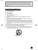
Page 100: ...outlet unless the blades can be fully inserted to prevent blade exposure CAUTION To reduce the risk of electric shock Do not remove cover or back No user serviceable parts inside Refer servicing to qualified service personnel The lightning flash with arrowhead symbol within an equilateral triangle is intended to alert the user to the presence of uninsulated dangerous voltage within the product s e...

Page 101: ...ves or other apparatus including amplifiers that produce heat 9 Do not defeat the safety purpose of the polarized or grounding type plug A polarized plug has two blades with one wider than the other A grounding type plug has two blades and a third grounding prong The wide blade or the third prong are provided for your safety If the provided plug does not fit into your outlet consult an electrician...

Page 102: ...uch as vases shall be placed on the apparatus 16 Avoid improper installation and never position the unit where good ventilation is impossible When installing this TV distance recommendations must be maintained between the set and the wall as well as inside a tightly enclosed area or piece of furniture Keep to the minimum distance guidelines shown for safe operation 17 Cautions for installation Do ...

Page 103: ...or cleaners directly on the TV s surface DO NOT rub or scrub the TV harshly Wipe the set gently with a soft cloth For example The screen is treated with an electrostatic proof coating When it gets dirty wipe it gently with a soft cloth If the screen is very dirty wipe it down with a cloth dipped in a diluted kitchen cleaner and thoroughly wrung out Then wipe immediately after with a clean dry clot...

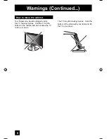
Page 104: ...rapped under the TV causing injuries Hold the TV at the bottom in the middle and do not allow the TV to tilt up or down The TV may fall causing injuries Hold the bottom of the stand with your hand and tilt the TV up or down How to move the cabinet ...

Page 105: ...tal In Audio 52 Picture Settings 53 Adjust Picture Settings 53 Color Temperature 53 Digital Noise Clear 54 Color Management 54 Dynamic Gamma 54 Smart Picture 55 Reset 55 Sound Settings 56 Adjust Sound Settings 56 Reset 56 Set Clock 57 On Off Timer 58 Multi Screen Function 59 Index 59 Twin 59 Freeze 60 Swap 60 Select 60 Power 61 Number Buttons 61 Tune 61 Input 61 TheaterPro D6500K 61 Return TV 62 S...

Page 106: ...n 76 Timer Edit 77 Guide 78 Readable Media Card 79 Supported Card Media 79 How to insert Media Card 80 How to operate Media Card Viewer 81 PHOTO 82 VIDEO 82 FILE 83 Operation Note 84 Specifications for Media Card Viewer 85 Weak Signal 86 No Program 86 Cable Card Connection 87 Troubleshooting 88 Warranty 90 Specifications 92 Notes 94 Digital Button Functions 73 Digital Setup 70 Cable Card Informati...

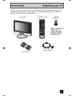
Page 107: ...ur television box should include INPUT INDEX ASPECT FREEZE SWAP SELECT RETURN FAVORITE THEATER PRO NATURAL CINEMA VIDEO STATUS TIMER i LINK MENU SOUND LIGHT TV CATV VCR DVD MUTING MENU BACK GUIDE RM C14G REW VCR CHANNEL PREV NEXT VCR DVD POWER TV VCR FF PLAY REC PAUSE OPEN CLOSE STILL PAUSE STOP CH CH VOL VOL OK MULTI SCREEN TWIN D A 1 2 3 4 5 6 7 8 9 0 TUNE TV POWER C C SUB CHANNEL SUB ML MTS SLE...

Page 108: ...TICAL OUT Digital Audio CABLE CARD CABLE CARD Quick Setup TV Models NOTE Before you connect your television to another device please refer to the proper diagrams for your specific TV and remote These will help assist you in understanding how to connect your television to another device as well as use the remote to set up your television Rear Panel Diagram Side Panel Diagram MEDIA CARD SLOT INPUT M...

Page 109: ...REC PAUSE OPEN CLOSE STILL PAUSE STOP CH CH VOL VOL OK MULTI SCREEN TWIN D A 1 2 3 4 5 6 7 8 9 0 TUNE TV POWER C C SUB CHANNEL SUB ML MTS SLEEP DISPLAY Quick Setup TV Remote Control RM C14G Notes For information on remote control buttons see pages 59 69 and 73 78 i LINK MENU TIMER SUB CHANNEL FAVORITE and GUIDE buttons are for digital channels If your TV is connected to an ATSC antenna or Digital ...

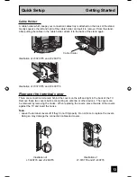
Page 110: ...right Step 1 Using the stand Tilt the TV up or down While holding the bottom of the stand with one hand use your other hand to hold the middle of the top of the TV and slowly tilt the TV up or down As a safety measure the stand is constructed so that it requires a certain amount of force to tilt the TV Rotate the TV left or right While holding the bottom of the stand with one hand use your other h...

Page 111: ...covers off if they do not fit properly Do not force to replace the covers Doing so may damage the connection cables and covers Cable Holder A cable holder which keeps your connection cables tidy is attached on the back of the stand Gently squeeze the left and right of the cable holder and pull it to remove it from the stand After putting the cables in the cable holder attach it to the back of the ...

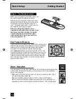
Page 112: ...idly through the channels using JVC s Hyperscan feature press and hold CH or CH The channels will zip by at a rate of five channels per second The right and left buttons will turn the volume up or down These buttons are also marked with four arrows and are used with JVC s onscreen menu system To use the onscreen menus press the MENU button MUTING MENU BACK GUIDE VCR CHANNEL VCR DVD CH CH VOL VOL O...

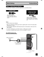
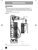
Page 113: ... Notes These connections are examples After you are finished connecting your devices plug the power cord into the nearest power outlet and turn on the TV If you follow these diagrams and the television does not work properly contact your local cable operator To connect a DVD player see VCR Connection A DVD player is optional If you have a satellite television system refer to the satellite TV manua...

Page 114: ...he cables You may also connect the DVD player to Input 1 DIGITAL IN 75Ω VHF UHF ATSC DIGITAL CABLE IN i LINK IN OUT S400 TS CABLE CARD TV Rear Panel INPUT 3 INPUT 2 INPUT 1 INPUT 1 COMPONENT DIGITAL IN AUDIO AUDIO OUT S VIDEO VIDEO R AUDIO L S VIDEO VIDEO R AUDIO L Y Pr Pb VIDEO R AUDIO L R AUDIO L R L OR IN OUT IN OUT V L R Cable or Antenna Output Two Way Splitter Attachment Coaxial Cable Attachm...

Page 115: ...NPUT 1 COMPONENT DIGITAL IN AUDIO AUDIO OUT S VIDEO VIDEO R AUDIO L S VIDEO VIDEO R AUDIO L Y Pr Pb VIDEO R AUDIO L R AUDIO L R L IN OUT IN OUT V L R Y PB PR OUT AUDIO OUT R L Two Way Splitter OR Cable or Antenna Output Two Way Splitter Attachment Coaxial Cable Attachment VCR Green Blue Red DVD Player OPTIONAL IN OUT OUT IN OUT OUT ...

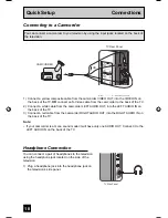
Page 116: ...f your camcorder is a mono sound model it will have only one AUDIO OUT Connect it to the LEFT AUDIO IN on the back of the TV You can connect a camcorder to you televison by using the input jacks located on the back of the television INPUT 3 INPUT 2 INPUT 1 S VIDEO VIDEO R AUDIO L S VIDEO VIDEO R AUDIO L VIDEO R AUD CAMCORDER OR TV Rear Panel Connecting to a Camcorder Headphone Connection You can c...

Page 117: ...ier Connecting to Monitor Recording Output Terminal Notes When you make this connection set the Video 1 Monitor Out menu to ON See page 51 If you are receiving ATSC Digital Cable signal it can be outputted to the S Video output terminal or Video composite video terminal If you are receiving Analog TV signal it can not be outputted to the S Video output terminal No signal will be outputted through ...

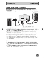
Page 118: ...er s MONITOR OUT into the VIDEO INPUT 1 on the back of your television 3 Connect a Green Component Cable from the AV Receiver s Y MONITOR OUT into the Y VIDEO INPUT 1 on the back of your television 4 Connect a Blue Component Cable from the AV Receiver s PB MONITOR OUT into the Pb VIDEO INPUT 1 on the back of your television 5 Connect a Red Component Cable from the AV Receiver s PR MONITOR OUT into...

Page 119: ... IN on the back of your television 2 Connect a red cable from the DTV decoder RIGHT AUDIO OUT to the RIGHT AUDIO DIGITAL IN on the back of your television 3 Connect a white cable from the DTV decoder LEFT AUDIO OUT to the LEFT AUDIO DIGITAL IN on the back of your television The digital in terminal is not compatible with the picture signal of a personal computer Use a HDMI to DVI cable commercially...

Page 120: ...IN ATSC DIGITAL CABLE IN CABLE CARD TV Rear Panel HDMI Compatible Device HDMI Cable L R AUDIO OUT DIGITAL OUT Connecting to a HDMI Compatible Device 1 Connect the HDMI Cable from the DIGITAL OUT on the back of your DTV or HDMI device to the DIGITAL IN on the back of your television Notes When you do the above connection set DIGITAL IN AUDIO in the Initial Setup menu to DIGITAL See DIGITAL IN AUDIO...

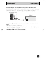
Page 121: ...utput can be PCM or Dolby Digital i LINK IN OUT S400 TS OPTICAL OUT Digital Audio Television Rear Panel Amplifier 1 Connect the optical cable from underneath the television to the back of the amplifier Notes This terminal can only output digital audio In order to use the optical output connection select PCM or Dolby Digital on Digital Sound in the Digital Setup Menu See page 71 Refer to your owner...

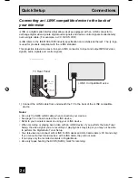
Page 122: ... OUT S400 TS i LINK Compatible Device TV Rear Panel OPTICAL OUT Digital Audio 1 Connect the i LINK cable from underneath the TV to the back of the i LINK compatible device Notes Use only the S400 i LINK cable when connection your devices See page 74 on how to select the i LINK device Refer to your owners manual on using your i LINK device When recording or playing back video with an i LINK device ...

Page 123: ...ng your television Notes The interactive plug in menu setting does not appear if your TV has been turned on before In this case use the onscreen menus to perform these settings See pages 45 57 35 If you press the Menu button while setting up the interactive plug in menu it will skip over it Step 4 The Interactive Plug In Menu Quick Setup Plug In Menu After the JVC INTERACTIVE PLUG IN MENU has been...

Page 124: ...r area you will have to set the clock manually See manual clock set below To set the clock using the XDS signal To choose AUTO To TIME ZONE To select your time zone Atlantic Eastern Central Mountain Pacific Alaska or Hawaii To move to D S T Daylight Savings Time To turn D S T ON or OFF To NEXT To Auto Tuner Setup Notes D S T can be used when it is set to ON in the SET CLOCK menu Only when the MODE...

Page 125: ...er Setup When the setup is finished THANK YOU SETUP IS NOW COMPLETE is displayed Your quick setup is now complete You can now begin watching your television or you can continue on in this guide for more information on programming your remote control or using the JVC onscreen menu system to customize your television viewing experience Notes If you want to cancel the Auto Tuner Setup press the MENU ...

Page 126: ...w Citizen Curtis Diamond Eagle Eastern GC Brand Gemini General Instrument Jerrold Hamlin Hitachi Macom Magnavox Memorex Movietime Oak Paragon Panasonic Philips Pioneer 024 032 025 051 032 022 051 058 059 024 032 025 029 034 032 051 022 043 065 024 025 026 027 020 021 022 057 023 072 074 040 041 042 045 058 064 049 024 049 050 051 054 033 030 032 051 039 037 048 055 056 060 071 073 063 028 029 030 ...

Page 127: ...020 000 033 045 024 037 051 049 050 089 064 083 084 081 000 001 023 045 058 093 027 081 024 023 003 JVC Kenwood 003 004 005 000 001 002 006 007 003 004 064 005 LXI 027 064 058 065 066 063 067 VCR Codes Magnavox Marantz Marta Memorex MGA Minolta Mitsubishi Multitech NEC Olympic Optimus Orion Panasonic Penney Pentax Philco Philips Pioneer Proscan Quasar Radio Shack 031 023 024 086 003 004 005 064 02...

Page 128: ...others listed If it does not respond to any of the codes try the search codes function on page 31 After you program your remote some DVD buttons may not work properly If so use the DVD player s remote Remote Programming DVD Codes Codes DVD Player Codes Codes Aiwa 043 Apex 040 054 055 Denon 020 037 Hitachi 031 JVC 000 Kenwood 035 020 Konka 039 Mitsubishi 025 Onkyo 041 052 Oritron 044 Panasonic 020 ...

Page 129: ...e with your equipment 5 Press RETURN TV to exit VCR DVD Search Codes Function 1 Slide the first 2 way selector switch to TV and the other 2 way selector switch to VCR or DVD 2 Press the VCR or DVD POWER and RETURN TV buttons Hold for at least three seconds and release 3 Press the VCR or DVD POWER button and see if the VCR or DVD responds 4 If there was a response press RETURN TV The codes are now ...

Page 130: ...ean press the CH or CH buttons Pressing the CH or CH buttons let you Move vertically in a main menu screen Move through a submenu screen Move to the next letter number or other choice in a submenu Back up to correct an error Scan through TV channels when not in a menu screen Left and right arrows mean press the VOLUME or VOLUME buttons to move left or right to Select a highlighted menu item Select...

Page 131: ... are highlighted in a different color To move to a different feature use the π arrows to move up or down the list When you press the up arrow at the top of the list or the down arrow at the bottom the next menu screen will appear Use the arrows to select an option from the highlighted feature Pressing MENU on the remote control will close the onscreen menu system and return you to normal televisio...

Page 132: ... PREVIOUS 3 5 ILLUMINATION LANGUAGE CLOSED CAPTION AUTO SHUT OFF XDS ID OFF ON ENG FRAN ESP LOW INITIAL SETUP 03 INITIAL SETUP 02 ON OFF ON INITIAL SETUP SELECT OPERATE EXIT MENU NEXT PAGE PREVIOUS 2 5 NOISE MUTING FRONT PANEL LOCK V1 SMART INPUT VIDEO INPUT LABEL POSITION ADJUSTMENT POWER INDICATOR LOW INITIAL SETUP 01 INITIAL SETUP SELECT OPERATE EXIT MENU NEXT PAGE PREVIOUS 1 5 VIDEO 1 MONITOR ...

Page 133: ...o TUNER MODE IN ANALOG To choose CABLE AIR or SKIP π To TUNER MODE IN DIGITAL To choose ATSC DIGITAL CABLE or SKIP Press the OK button to start Programming will take approximately 2 to 4 minutes The auto tuner is finished when the message PROGRAMMING OVER appears onscreen Press the Menu button when finished AUTO TUNER SETUP SELECT OPERATE EXIT MENU IN ANALOG IN DIGITAL ATSC TUNER MODE AIR TUNER MO...

Page 134: ...up did not find them π To the SCAN column Press the OK button to include or delete from scan Press the MENU button when finished CHANNEL SUMMARY 06 07 08 09 10 CHNO SELECT OPERATE EXIT MENU 01 02 03 04 05 OK SCAN CHNO SCAN ID ID MTV A E E HBO L Channel Summary Digital CH No Operate Back BACK Exit MENU Scan FOX ABC CNN NBC BOX NHK Station Name D01 D02 D02 D10 1 D10 2 D12345 Analog Channels Digital ...

Page 135: ...ton π To CHANNEL SUMMARY To operate π To the ID column Press the OK button to enter π To select RESET Press the OK button to finish Your characters are now reset Notes You can use characters for Alphabet numbers marks and spaces It is possible to set the maximum of 40 channel labels If you try to set more than the 40 maximum the message MEMORY OVERFLOW will appear You can block access to a channel...

Page 136: ...es To access the rating categories Press the MENU button π To V CHIP To operate Lock icon will appear Press ZERO to access the V Chip menu To turn V Chip ON or OFF V Chip must be turned ON for rating settings to operate π To move to SET US TV RATINGS SET MOVIE RATINGS or SET CANADIAN RATINGS see following pages for descriptions of each item V Chip Your TV is equipped with V Chip technology which e...

Page 137: ...ogramming on television stations which do not broadcast rating signals will be placed in the Unrated Programming category Examples of Unrated programs Emergency Bulletins Locally Originated Programming News Political Programs Public Service Announcements Religious Programs Sports Weather Some Commercials Note TV programs or movies that do not have rating signals will be blocked if the unrated cate...

Page 138: ...trong language limited violence and some suggestive sexual dialog or situations It is recommended that parents watch these programs first or with their children TV 14 Parents Strongly Cautioned Programs contain some material that may be unsuitable for children under the age of 14 including possible intense violence sexual situations strong coarse language or intensely suggestive dialog Parents are...

Page 139: ...he OK button to lock Press the MENU button when finished Note If you want to change the setup move the cursor to the top column and change the lock icon to by pressing OK again You may then select individual categories to block Directions to set US V Chip Ratings Press the MENU button π To V CHIP To operate lock icon appears Press ZERO to access the V Chip menu To turn V Chip ON or OFF π To move t...

Page 140: ...re cautioned that the content of movies with this rating may include more explicit sexual language and violence content than movies rated PG R Restricted These films contain material that is explicit in nature and is not recommended for unsupervised children under the age of 17 NC 17 No One Under 17 These movies contain content which most parents would feel is too adult for their children to view ...

Page 141: ...t and limited to portrayals that are clearly imaginary comedic or unrealistic in nature C8 Programming Intended for Children 8 and Over Violence Guidelines Any realistic depictions of violence will be infrequent discreet of low intensity and will show the consequences of the acts There will be no offensive language nudity or sexual content G General Audience Programming will contain little violenc...

Page 142: ...K button to finish your lock code is now set Press the Menu button when finished After a power interruption you must reset the lock code Write your lock code number down and keep it hidden from potential viewers If you forget the lock code a new code may be set using the steps listed above Notes When a viewer attempts to watch a blocked channel this message appears The channel will remain blocked ...

Page 143: ...t remains on when illumination is set to LOW or HIGH Press the Menu button π To ILLUMINATION To choose HIGH LOW or OFF Press the MENU button when finished Illumination INITIAL SETUP SELECT OPERATE EXIT MENU NEXT PAGE PREVIOUS 3 5 ILLUMINATION LANGUAGE CLOSED CAPTION AUTO SHUT OFF XDS ID OFF ON ENG FRAN ESP LOW The language function is described on page 25 as the interactive plug in menu If you nee...

Page 144: ...l Setting Closed Caption Analog Setting Digital Auto Setting Press the MENU button π To CLOSED CAPTION To enter π To Type To select Auto Advanced or Basic Auto Shows closed caption a priority for digital channels over analog channels It is set automatically Advanced Shows only the digital closed caption Basic Shows only the analog closed caption π To Service To select 1 2 3 4 5 or 6 π To Appearanc...

Page 145: ...π To Set Press the OK button to save π To Colors To enter π To select Text Edge or Background To select the setting you like Auto White Black Red Green Blue Yellow Magenta or Cyan π To Set Press the OK button to save π To Opacities To enter π To select Text Edge or Background To select Auto Transparent Translucent Solid or Flashing π To Set Press the OK button to save Press the MENU button when fi...

Page 146: ...shuts itself off When i LINK is displayed Auto Shut Off will not work Auto Shut Off INITIAL SETUP SELECT OPERATE EXIT MENU NEXT PAGE PREVIOUS 3 5 ILLUMINATION LANGUAGE CLOSED CAPTION AUTO SHUT OFF XDS ID OFF ON ENG FRAN ESP LOW XDS ID Display provides a channel s call letters the network s name and even a program name The XDS ID information is provided by the broadcaster Press the MENU button π To...

Page 147: ...s you to lock the keys on the side of the TV so that a child may not accidentally change your viewing preferences Press the MENU button π To FRONT PANEL LOCK To turn ON or OFF Press the MENU button when finished Front Panel Lock You can turn off this feature in the following ways Unplug the power cord and plug it back in Do this if your batteries die or you lose your remote control Use the remote ...

Page 148: ...perate π To select the desired video input To select the desired preset input label see chart below Press the OK button to save Press the MENU button when finished INITIAL SETUP SELECT OPERATE EXIT MENU NEXT PAGE PREVIOUS 2 5 LOW ON OFF ON NOISE MUTING FRONT PANEL LOCK V1 SMART INPUT VIDEO INPUT LABEL POSITION ADJUSTMENT POWER INDICATOR Video Input Label Preset Labels VCR DVD DVHS STB SAT AMP GAME...

Page 149: ...ess the OK button When the arrow disappears while you are adjusting the position the position is at it s maximum limit If you select regular size and slim size with aspect or Multi Screen position adjustment option is not seen When you change the screen size perform the position adjustment again Position adjustment allows you to adjust the screen position vertically and horizontally when the aspec...

Page 150: ...l select SIZE1 or SIZE2 automatically Digital In INITIAL SETUP SELECT OPERATE EXIT MENU NEXT PAGE PREVIOUS 1 5 VIDEO 1MONITOR OUT DIGITAL IN DIGITAL IN AUDIO OFF SIZE1 DIGITAL This feature is used if you have a DTV or HDMI compatible component connected to your TV Press the MENU button π To DIGITAL IN AUDIO To select ANALOG DIGITAL or AUTO Press the Menu button when finished Notes If your DTV or H...

Page 151: ...ightness of the TV picture with the Bright control DETAIL The Detail feature adjusts the level of fine detail displayed in the picture ENERGY SAVER MODE The energy saver mode adjusts the level of brightness on the TV screen Picture Adjust Picture Settings Adjust the Picture Settings Color Temperature You can decide how strong or dull the colors appear on the TV screen Press the MENU button π To CO...

Page 152: ...nished COLOR MANAGEMENT ON OFF Dynamic Gamma JVC s Dynamic Gamma Circuitry DGC makes it easier to see dark areas when a picture has many dark areas and makes it easier to see the bright areas when a picture has many bright areas DGC is turned on DGC analyzes and adjusts the total level of picture brightness balance especially in dark areas where the level of greyscale is often lost turning complet...

Page 153: ... picture adjustments Press the MENU button when finished SELECT OPERATE EXIT MENU NEXT PAGE PREVIOUS STANDARD PICTURE ADJUST 2 2 OFF OFF OFF ON COLOR TEMPERATURE DIG NOISE CLEAR COLOR MANAGEMENT DYNAMIC GAMMA SMART PICTURE RESET HIGH Smart Picture Smart Picture detects the APL Average Picture Level and adjusts the contrast suitable for what you are watching Press the MENU button π To SMART PICTURE...

Page 154: ...on π To BASS TREBLE or BALANCE To adjust the setting π To move to the next setting Press the MENU button when finished Note You can reset the sound adjustments BASS TREBLE and BALANCE you set at once as the default setting when you select reset See page 55 You can adjust BALANCE only when A H S is off See page 62 Sound Adjust Sound Settings Adjust the Sound Settings BASS TREBLE BALANCE RESET SOUND...

Page 155: ...EAR To set the month π To day To set the day π To year To set the year π To D S T daylight savings time To turn D S T ON or OFF Press OK to start clock Press the MENU button when finished SET CLOCK PRESS TO START CLOCK SELECT OPERATE EXIT MENU OK TIME MODE TIME ZONE DATE YEAR D S T MANUAL ATLANTIC JAN 01 05 ON SET CLOCK PRESS TO FINISH SELECT OPERATE EXIT MENU OK TIME MODE TIME ZONE DATE YEAR D S ...

Page 156: ...way as ON TIME To accept OFF TIME and move to CHANNEL To select channel To ON VOLUME To set the volume level To move to MODE Choose ONCE or EVERYDAY To ON OFF TIMER Choose YES to accept the timer setting choose NO if you don t wish to accept Press the OK button to finish Press the MENU button to exit the menu The on off time cannot be set to locked or guarded channels In order for the on off timer...

Page 157: ... the signal that you are watching is coming from the HDMI input you cannot enter the SWAP or INDEX mode Main Screen and Split Screen will not display the same channel or input at the same time You can enter the TWIN mode when the screen is in NORMAL or INDEX mode Split screen functions will not work with locked channels or channels blocked by V Chip ratings limits A grey screen will display instea...

Page 158: ...SPLIT screen When you press SELECT button the channel number on the top will be highlighted Each press of SELECT will shift the channel Select Note When the screen is in freeze mode if you do not operate it within 15 minutes this function will cancel out Pressing the FREEZE button causes the screen to change to the split screen display with the still picture displayed on the right In order to retu...

Page 159: ...ry press of the INPUT button you can change the input mode Notes When you return to TV mode press the RETURN TV button or direct 10 key pad or CHANNEL button You can also access by pressing the INPUT button on the side of the TV instead of the remote control i LINK can be selected only when you have an i LINK device connected Input Lets you decide the input channel and select it After you press th...

Page 160: ...OUND button you can change the A H S Advanced Hyper Surround mode BBE SMART SOUND and A H B Active Hyper Bass on or off A H S Adds a more spacious surround sound Music gives basic effect and movie for more effect BBE BBE High Definition Sound restores clarity and presence for better speech intelligibility and musical realism SMART SOUND Decreases high sound levels giving a regulated sound level A ...

Page 161: ... FRONT CONTROL PANEL screen by using the MENU button on the side of the TV instead of the remote control It appears between INITIAL SETUP and PICTURE ADJUST screen and it has VIDEO STATUS and ASPECT menus Choose VIDEO STATUS by pressing MENU on the side panel and choose a mode by using the CHANNEL buttons OPERATE Video Status VIDEO STATUS STANDARD DYNAMIC THEATER GAME Natural cinema corrects the p...

Page 162: ...r stereo sound an MTS broadcast may also include a second audio program SAP Press the ML MTS button By every press of the ML MTS button you change the mode Notes When you are receiving a digital broadcast if there are other languages you can change the language by pressing the ML MTS button Keep the TV in stereo mode to get the best sound quality The sound will work in stereo mode even if a certai...

Page 163: ...re not set the display screen will show CLOCK NOT SET SLEEP TIMER OFF and ON OFF TIMER OFF respectively Display 05 KLVX PBS JAZZ FESTIVAL NOW SLEEP TIMER ON OFF TIMER ON TIME OFF TIME 12 20 PM OFF EVERYDAY 7 00 PM 10 00 PM Display Time Channel Off C C Closed Caption Use the C C Closed Caption button to select the mode of closed caption Press the C C button Notes SMART CAPTION will appear when you ...

Page 164: ... The digital channels have a D in front of the channel number The maximum number of channels you can register is 24 If you have registered the maximum number of channels and try to register more channels the oldest channel you registered will be deleted Sub channels can not be registered The newest channel you registered will appear at the top of the list Regarding digital channels see pages 73 78...

Page 165: ...Aspect Ratios PANORAMA With this ratio a normal 4 3 aspect picture is stretched to fit the dimensions of the 16 9 aspect screen CINEMA This ratio zooms in on the center part of a 4 3 aspect picture blowing it up to fill the 16 9 screen FULL This is the ratio to use when watching 16 9 High Definition broadcasts PANORAMA ZOOM This ratio stretches the High Definition 16 9 aspect image to eliminate th...

Page 166: ...dispalyed when the signal is ATSC 480i or 480p If the televison receives a 16 9 signal from your HDMI device the aspect mode will turn to FULL automatically If the television receives a 4 3 signal from your HDMI device when you are in FULL aspect mode it will return to REGULAR aspect mode If you change the aspect mode after the televison changed it to FULL automatically the televison will change t...

Page 167: ...an also use this remote control to operate the basic functions of your DVD player These functions include play rewind fast forward stop still pause previous next tray open close power on and power off Move the selector switch to DVD to operate The remote is preset with the code 000 to control JVC brand DVD players For any other manufacturer s brand DVD player please see the code chart and instruct...

Page 168: ... blank In this case the tuner will switch to digital since you are accessing the digital setup menu Digital Setup Digital Setup Select Back BACK Exit MENU Operate PCM 4 3 OFF Antenna Level Digital Sound Aspect Ratio Cable Card Application i LINK Auto Play Software Update Confirms the present antenna level Press the MENU button π To DIGITAL SETUP To enter π To Antenna Level To enter Note If you are...

Page 169: ...Manufactured under license from Dolby Laboratories Dolby and the double D symbol are trademarks of Dolby Laboratories You can select the optical digital sound output either PCM or Dolby Digital when your TV is connected to an amplifier that has Dolby Digital decoder If you select Dolby Digital you can enjoy listening in 5 1ch sound when watching digital broadcasts Press the MENU button π To DIGITA...

Page 170: ...d Software Update When playing a D VHS tape you can set it to the i LINK input automatically or manually Press the MENU button π To DIGITAL SETUP To enter π To i LINK Auto Play To select ON or OFF ON Set to i LINK input automatically OFF Select the input manually Press the MENU button when finished i LINK Auto Play Digital Setup Press the MENU button π To DIGITAL SETUP To enter π To Cable Card App...

Page 171: ...ou can select a digital channel only Press the D A button To watch digital channels For example to move to channel D23 Press 2 Two Press 3 Three Press the TUNE button The main channel sometimes has minor channels Sub Channels By using the SUB button you can select a sub channel easily For example to move to sub channel 123 45 Press 1 One Press 2 Two Press 3 Three Press the SUB button Press 4 Four ...

Page 172: ...K cable see page 24 When operating the i LINK don t insert or disconnect the i LINK cable Controller You can operate a D VHS VCR connected with an i LINK cable by using this controller Notes If the i LINK is not connected the Controller OSD will not appear The OSD of device on page 75 will appear Some controller operations may differ from your D VHS VCR operations Press the i LINK MENU button π To...

Page 173: ...he Controller onscreen The devices listed on the device onscreen are only D VHS and HD MOVIE that have i LINK which can be recognized on this television However you can not record programs to HD MOVIE If you disconnect one device it will be removed from the list Then select Renumber to rearrange the list in the new order i LINK Controller Renumber Device D VHS1 HM DH30000U D VHS2 HM DH40000U JVC H...

Page 174: ... added in front of the program title If you set the View on timer mode set viewing is added in front of the program title Notes In order for the timer setting to work you must set the clock on your television See page 57 When you want to edit the timer settings see Timer Edit on page 77 Digital Button Functions Timer R V V R R R 80 3 PBS1DTV Sep 11 Wed 6 00PM 6 30PM Once 335 1 KDVRet Retailer News...

Page 175: ...t you want to delete Press the OK button π To Delete Press the OK button Digital Button Functions V R R R 80 3 PBS1DTV Sep 11 Wed 6 00PM 6 30PM Once 335 1 KDVRet Retailer News Channel Sep 11 Wed 6 00PM 7 00PM Mon Fri 335 1 KDVRet Regular Schedule Sep 18 Wed 5 00PM 6 00PM Daily 35 1 PBPBPB Sep 18 Wed 8 00PM 8 30PM Weekly i LINK i LINK 0 New Reservation Page 1 3 Sept 10 Wed 4 55PM Timer New Reservat...

Page 176: ... digital program now you can cancel the recording Press the TIMER button π To select the timer list you want to cancel the recording Press the OK button The message Do you want to terminate current program will appear To select YES Cancel the recording NO Continue the recording Press the OK button V R 80 3 PBS1DTV Sept 11 Wed 6 00PM 6 30PM Once 335 1 KDVRet Retailer News Channel Sept 11 Wed 6 00PM...

Page 177: ...f data already recorded on the card Playback of MPEG 2 video on CompactFlash cards requires a high speed type card Conversion adapters for card media are not supported The unit may have trouble detecting certain cards In this case leave the card inserted and turn the power off and then on again Recognition of the card can take significantly more time if the card contains a large number of files Th...

Page 178: ...it Once you have inserted the media card the message PLEASE CLOSE THE DOOR TO OPERATE will appear on the screen Then close the door To remove the media card press the card into the slot again after opening the door Ridge Metal Terminal Removable Microdrive Hard Disk does not have a ridge PUSH OPEN Close door when using media cards COMPACT FLASH SD MMC MEMORY STICK xD Picture Card xD Picture Memory...

Page 179: ...ing cases When you are inserting a media card or when the door is open PLEASE CLOSE THE DOOR TO OPERATE When no media card is inserted NO MEDIA DETECTED When no files are found on the media card NO FILE FOUND Press the MENU button π To MEDIA CARD VIEWER To enter π To select SD Card or COMPACT FLASH card If you only have one media card inserted in the card slot this menu will not appear To enter Th...

Page 180: ...ress π while the image is paused and you can rotate the image Notes Although the image has changed because it is rotated it will not be saved to the media card When rotation is performed the aspect ratio of the image may change The angle of view may also change for some images VIDEO Select VIDEO Press the OK button The right nine images appear π To select an image that you like Press the OK button...

Page 181: ...re playing back with this unit The audio cannot be played unless the mpg extension is changed The extension for images recorded in Everio is mod but the extension is automatically changed to mpg after editing with CyberLink DVD Solution You may not be able to replay audio on some files created or edited with CyberLink DVD Solution software provided with some JVC digital cameras This will depend up...

Page 182: ...buttons CH Fast Forward CH Rewinding VOL Up volume VOL Down volume OK Pause or Play Each pressing will switch back and forth 2 When you select FILE icon and play the PHOTO or VIDEO While playing PHOTO You cannot use CH CH and VOL While playing VIDEO You cannot use CH You can change volume by using VOL Note While using the card viewer do not unplug the television from the AC outlet It will cause th...

Page 183: ...image file standards and extensions 1 Exif 2 21 Extensions JPG jpg JPEG jpeg 2 JFIF Extensions JPG jpg 3 SD Video MPEG2 PS Extensions MOD mod MPG mpg MPEG mpeg 4 SD Video ASF MPEG4 Extensions ASF asf 5 Supported image size and rate 1 Still images 160 120 to 2560 1920 pixels The size is automatically adjusted when displayed 2 Video 1 MPEG2 PS 720 480 pixels 525 60 systems 352 240 pixels 525 60 syst...

Page 184: ...r were watching is not receiving a signal NO PROGRAM appears on the television screen It appears when that channel is not receiving a signal and you have the Noise Muting function OFF and you have a single screen It moves automatically every two seconds to prevent the screen from burn in Note Even if NO PROGRAM appears on the screen your timer functions and auto shut off functions that you set are...

Page 185: ...se the program information is being renewed This is normal Cable Card Connection DIGITAL IN ATSC DIGITAL CABLE IN CABLE CARD Cable Card Note for inserting Cable Card When you are watching a digital program and if a weather or government emergency occurs the following may occur automatically regardless of what channel you were watching the channel may change the screen will disappear or important t...

Page 186: ...hannel Summary Lock page 37 Make sure the set did not become unplugged Perhaps the On Off Timer is set See page 58 Check to see if the Sleep Timer was set See page 64 The power was interrupted and the clock was not reset See page 57 Tint and Color may be improperly adjusted See page 53 The Video Status mode may be turned to the wrong setting See page 63 There could be interference from another ele...

Page 187: ...u programed has occured It does not operate correctly Press the CHANNEL and VOLUME buttons on the side panel of the TV simultaneously for a few seconds The Digital Tuner will be reset If this does not reset it correctly unplug the power cord and plug it back in The following are not malfunctions The television may make a creaking sound if the temperature of the room or the temperature of the insid...

Page 188: ...90 ...

Page 189: ...91 ...

Page 190: ...n terminal is not compatible with picture signals of a personal computer Refer to unpacking your TV page 9 Dimensions inch cm W X H X D Weight lbs kg Accessories LT 32X776 Monitor Recording Output Video 1Vp p 75ohms Y 1Vp p positive 75 ohms negative sync provided C 0 286 Vp p burst signal 75 ohms Audio 250mVrms 10dBs Fs 18dB Low Impedance Optical Output Digital Audio Digital Out optical x 1 i LINK...

Page 191: ...ght lbs kg Accessories Monitor Recording Output Video 1Vp p 75ohms Y 1Vp p positive 75 ohms negative sync provided C 0 286 Vp p burst signal 75 ohms Audio 250mVrms 10dBs Fs 18dB Low Impedance Optical Output Digital Audio Digital Out optical x 1 i LINK In Out Jack TS IN OUT 4 pin S400 x 2 IEEE1394 compliant DTCP digital copy protection compatible LT 37X776 202W 37 inch 94 9 cm measured diagonally 1...

Page 192: ...94 Notes ...

Page 193: ...95 Notes ...

Page 194: ...JVC COMPANY OF AMERICA Division of JVC Americas Corp 1700 Valley Road Wayne New Jersey 07470 JVC CANADA INC 21 Finchdene Square Scarborough Ontario Canada M1X 1A7 ...

Reviews: