background image

1-18 (No.YA682<Rev.001>)

4.5.6 VSM PRESET MODE

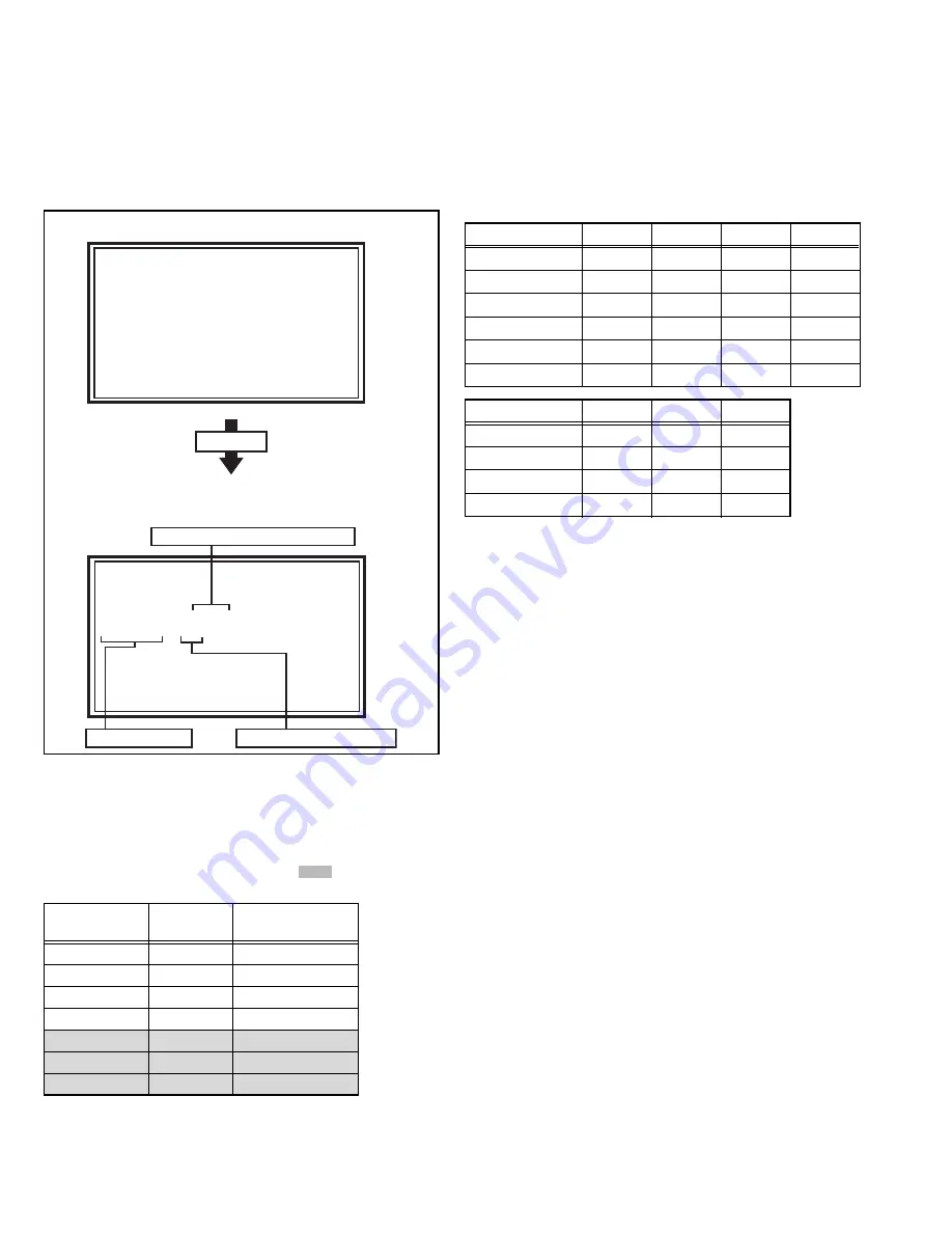
This mode is used to adjust the VSM.

4.5.6.1

HOW TO ENTER THE VSM PRESET MODE

When the SERVICE MENU SCREEN of SERVICE MODE is
displayed, press 

[6]

 key to enter the VSM PRESET MODE.

4.5.6.2

DESCRIPTION OF STATUS DISPLAY

(1) PICTURE MODE / COLOUR TEMP.

The picture mode / colour temp. displayed on the screen is
displayed.

(2) SETTING ITEM NAME

Setting item name are displayed. 

(3) SETTING VALUE (DATA)

The SETTING VALUE is displayed. The setting value to be
displayed are listed below.

NOTE:

4.PRIMCON has a special adjustment operation different from
the other standard adjustment.

It is because PRIMCON has a wide range of variable.

4.6

INITIAL SETTING VALUES IN THE SERVICE MODE

• Perform fine-tuning based on the "initial values" using the remote control when in the Service mode.
• The "initial values" serve only as an indication rough standard and therefore the values with which optimal display can be achieved

may be different from the default values. 

• Never change the values of the items ( 

 ) that are not described in ADJUSTMENT PROCEDURE or in the below table as they

are fixed values.

VSM Preset 


BRIGHT

1. CONTRAST       XXXX

   OK:Store    i:Exit

Service Menu

1.Adjust
2.Self Check
3.I2C Stop

Press [6] key

(1) PICTURE MODE/COLOUR TEMP.

(3) SETTING VALUE (DATA)

(2) SETTING ITEM

SERVICE MODE SCREEN

VSM PRESET MODE SCREEN

Item name

BRIGHT

STD

SOFT

GAME

1.CONTRAST

+2

0

0

0

2.BRIGHT-1

+16

+10

0

0

3.BRIGHT-2

0

0

0

0

4.SHARP

+2

0

0

0

5.COLOUR

+2

0

0

0

6.HUE

0

0

0

0

Item name

Cool

Normal

Warm

1.R DRIVE

0

0

0

2.G DRIVE

-9

0

-5

3.B DRIVE

-5

0

-1

4.PRIMCON

10800

9300

6800

[RED]

 key: +100

[GREEN]

 key: -100

[YELLOW]

 key: +10

[BLUE]

 key : -10

Item name

Variable 

range

Setting value

1.SC ADJ.

0 - 63

14

2.R DRIVE

0 - 1024

512

3.G DRIVE

0 - 1024

512

4.B DRIVE

0 - 1024

512

5.CUTOFF R

-1024 - 1023

0

6.CUTOFF G

-1024 - 1023

0

7.CUTOFF B

-1024 - 1023

0

Summary of Contents for LT-42R10BU/PP

Page 1: ...2R10BU PP COPYRIGHT 2009 Victor Company of Japan Limited FT4 CHASSIS LINEUP TABLE OF CONTENTS 1 PRECAUTION 1 3 2 SPECIFIC SERVICE INSTRUCTIONS 1 6 3 DISASSEMBLY 1 10 4 ADJUSTMENT 1 16 5 TROUBLESHOOTING 1 21 BASIC CHASSIS FT4 No YA595 LT 42DR9 series No YA596 LT 42R90BU No YA660 LT 32DR9 series No YA661 LT 32R90BU No YA681 LT 32R10BU No YA682 LT 42R10BU ...

Page 2: ...V inch wide aspect 16 9 Screen Size Diagonal 105 cm H 93 0 cm V 52 3 cm Display Pixels Horizontal 1920 dots Vertical 1080 dots W UXGA Audio Power Output 10 W 10 W Speaker 4 0 cm 16 0 cm oblique type 2 Aerial Terminal VHF UHF 75 Ω unbalanced coaxial EXT 1 EXT 2 Input Output 21 pin Euro connector SCART socket 2 EXT 3 Input Component Video 750p 1125i 1125p 625p 525p 625i 525i RCA pin jack 3 Y 1 V p p...

Page 3: ...onents that indicate evidence of overheating should be replaced Always use the manufacturer s replacement components 6 Isolation Check Safety for Electrical Shock Hazard After re assembling the product always perform an isolation check on the exposed metal parts of the cabinet antenna terminals video audio input and output terminals Control knobs metal cabinet screw heads earphone jack control sha...

Page 4: ...use damages even when the unit is carefully packed To prevent accidents from occurring during transportation pay careful attention before delivery such as through explaining the handling instructions to transporters Ensure that the following requirements are met during transportation as the LCD panel of this unit is made of glass and therefore fragile 1 USE A SPECIAL PACKING CASE FOR THE LCD PANEL...

Page 5: ...or parts the front LCD panel should be placed facing downward Place a mat etc underneath to avoid causing scratches to the front filter surface 1 3 4 HOW TO CHECK THE OPERATING TIME This model has a function to count and record the LCD panel operating time The operating time can be checked in the following procedure Maximum count time 131072 hours 1 Press the INFORMATION key and MUTING key simulta...

Page 6: ...UDIO R input 500mV rms Nominal High impedance Used R1 Used R2 3 AUDIO L output 500mV rms Nominal Low impedance Used TV OUT Used LINE OUT 4 AUDIO GND Used Used 5 GND B Used Used 6 AUDIO L input 500mV rms Nominal High impedance Used L1 Used L2 7 B input 700mV B W 75Ω Used Not used 8 FUNCTION SW SLOW SW Low 0V 3V High 8V 12V High impedance Used Used 9 GND G Used Used 10 SCL T V LINK Not used Used SCL...

Page 7: ...rightness twice as brighter as originally lighting For checking this pixel fault input 100 of each R G B colour and find out the cell that is not lighting FLICKER FAULT In the pixel fault a cell that should light originally or not light originally is flashing on and off For checking this pixel fault input ALL BLACK SCREEN signal or 100 of each RGB colour and find out the cell that is flashing on a...

Page 8: ...r supply 70 LINE_IN3R I Not used 71 LINE_IN3L I Not used 72 GND GND 73 LINE_IN2R I Not used 74 LINE_IN2L I Not used 75 GND GND 76 LINE_IN1R I Not used 77 LINE_IN1L I Not used 78 VREFAU I Reference voltage setting 79 HP_R O Audio for headphone 80 HP_L O Audio for headphone 81 MAIN_OUT_SUB O Not used 82 M_R O Audio for speaker 83 M_L O Audio for speaker 84 GND GND 85 VDD10_HDMI1 2 1V power supply 86...

Page 9: ...supply 201 VDD25_DRAM 2 5V power supply 202 VDD10_DLL 1V power supply 203 VDD25_DRAM 2 5V power supply 204 TE2 O LVDS data for LCD panel 205 TE2 O LVDS data for LCD panel 206 VDD25_VOPA 2 5V power supply 207 TD2 O LVDS data for LCD panel 208 TD2 O LVDS data for LCD panel Pin Pin name I O Function 209 GND GND 210 TCLK2 O LVDS clock for LCD panel 211 TCLK2 O LVDS clock for LCD panel 212 VDD25_VOPA 2...

Page 10: ...EAR COVER Remove the POWER CORD 1 Remove the 6 screws D 2 Remove the POWER PWB 3 2 3 REMOVING THE MAIN PWB Fig 3 1 Remove the REAR COVER 1 Remove the 1 screw E 2 Remove the TERMINAL BASE 3 Remove the 4 screws F 4 Remove the MAIN PWB 3 2 4 REMOVING THE REMOTE PWB Fig 3 1 Remove the REAR COVER 1 Remove the 1 screw I 2 Remove the REMOTE PWB 3 2 5 REMOVING THE SW PWB Fig 3 1 Remove the REAR COVER 1 Re...

Page 11: ...L F D K C B A REAR COVER POWER PWB MAIN PWB MAIN BASE SW PWB CONTROL ASSY FRONT PANEL SPEAKER LCD SUPPORT BRACKET LCD SUPPORT BRACKET LCD SUPPORT BRACKET LED PWB BOTTOM FRAME REMOTE PWB SPEAKER TERMINAL BASE STAND POWER CORD POWER CORD COVER LCD SUPPORT BRACKET a a B ...

Page 12: ...2 11 REMOVING THE INVERTER PWB Fig 3 2 Remove the REAR COVER Remove the SIDE BRACKET 1 Remove the 6 screws B 2 Remove the INVERTER PWB COVER 3 Remove the INVERTER PWB 4 Follow the same steps when removing the other INVERTER PWB Fig 3 2 ZZZ ZZZ ZZZ ZZZ ZZZ ZZZ ZZZ ZZZ ZZZ ZZZ ZZZ ZZZ INVERTER PWB COVER LCD CONTROL PWB COVER B A B INVERTER PWB MASTER INVERTER PWB SLAVE LCD CONTROL PWB LCD PANEL UNIT...

Page 13: ... these do not agree refer to the OPERATING INSTRUCTIONS and set the items as described 6 SERVICE MODE setting Verify what to set in the SERVICE MODE and set whatever is necessary Fig 3 3 Refer to the SERVICE ADJUSTMENT for setting 3 3 3 SERVICE MODE SETTING SERVICE MODE SCREEN Fig 3 3 SETTING ITEM Symbol Number of pins Mounting PWB Main content of data IC7003 8 pin MAIN PWB Setting value of IC7001...

Page 14: ... On Movie Theatre Off Colour Management On Picture Management On Smart Picture On Dynamic Backlight On MPEG Noise Reduction On Colour System TV Depends on PR CH EXT Auto 4 3 Auto Aspect Panoramic Setting item Setting position STEREO I II Stereo sound Bass Centre Treble Centre Balance Centre Hyper Sound Off MaxxBass Low 3D CINEMA SOUND Sorrund Mid Bass Boost Mid Auto Volume Control Off Setting item...

Page 15: ...ith the tweezers and remove the chip part Transistors diodes variable resistors etc 1 Apply extra solder to each lead 2 As shown in the figure push the part with tweezers and alternately melt the solder at each lead Shift and remove the chip part NOTE After removing the part remove remaining solder from the pattern 2 How to install Chip parts Resistors capacitors etc 1 Apply solder to the pattern ...

Page 16: ...l unit 4 4 ADJUSTMENT ITEMS VIDEO CIRCUIT COLOUR DECODER adjustment WHITE BALANCE HIGH LIGHT adjustment 4 5 BASIC OPERATION OF SERVICE MODE 4 5 1 HOW TO ENTER THE SERVICE MODE 1 Press INFORMATION key and MUTING key on the remote control unit simultaneously to enter the SERVICE MODE SCREEN NOTE Before entering the SERVICE MODE confirm that the setting of VCR TV DVD switch is at the TV side If the s...

Page 17: ...SERVICE MODE SCREEN ADJUST MODE SCREEN 480 60i 480i Component HDMI 480i 576 50i 576i Component HDMI 576i 480 60p 480p Component HDMI 480p 480 60p VGA HDMI 480p VGA 576 50p 576p Component HDMI 576p 720 50p 720p 50Hz Component HDMI 720p 50Hz 720 60p 720p 60Hz Component HDMI 720p 60Hz 1080 60i 1080i 60Hz Component HDMI 1080i 60Hz 1080 50i 1080i 50Hz Component HDMI 1080i 50Hz 1080 60p 1080p 60Hz Compo...

Page 18: ...de The initial values serve only as an indication rough standard and therefore the values with which optimal display can be achieved may be different from the default values Never change the values of the items that are not described in ADJUSTMENT PROCEDURE or in the below table as they are fixed values VSM Preset BRIGHT 1 CONTRAST XXXX OK Store i Exit Service Menu 1 Adjust 2 Self Check 3 I2C Stop...

Page 19: ...i DTV EPG DTV TEXT TWIN 12 SHARP 0 63 32 35 32 32 13 CORING 0 63 2 20 0 0 Item name Variable range Setting value Component 480i Component 576i Component 480p Component 576p Component 720p50 Component 1080i50 12 SHARP 0 63 32 32 32 32 32 13 CORING 0 63 2 2 2 2 2 Item name Variable range Setting value Component 720p60 Component 1080i60 Component 1080p50 Component 1080p60 Component 1080i50 Component ...

Page 20: ...LOUR 6 HUE 1 Select 6 VSM Preset from the SERVICE MODE 2 Set PICTURE MODE to Bright with the OK key 3 Set values of 1 CONTRAST 6 HUE to the initial setting values 4 Set PICTURE MODE to Standard with the OK key 5 Set values of 1 CONTRAST 6 HUE to the initial setting values 6 Set PICTURE MODE to Soft with the OK key 7 Set values of 1 CONTRAST 6 HUE to the initial setting values 8 Set PICTURE MODE to...

Page 21: ...ng the AC power cord plug when in the Self check display mode To Clear Reset Failure History Turn off the power by pressing the POWER key on the remote control unit when in the Self check display mode 5 1 4 FAILURE HISTORY Failure history can be counted up to 9 times for each item When the number exceeds 9 display will remain as 9 Failure history will be stored in the memory unless it has been del...

Page 22: ...t checks whenever I2 C communication is performed and no reply of ACK signal an error will be counted AUDIO AIO Confirmation of reply of ACK signal which uses I2C communication IC6661 MAIN PWB SDA If it checks whenever I2C communication is performed and no reply of ACK signal an error will be counted RF ANALOG TUNER TUN Confirmation of reply of ACK signal which uses I2 C communication TU1001 MAIN ...

Page 23: ...BASIC CHASSIS FT4 DVD ROM No SML2008Q4 COPYRIGHT 2009 Victor Company of Japan Limited No YA682 Rev 001 2009 2 SCHEMATIC DIAGRAMS WIDE LCD PANEL TELEVISION LT 42R10BU PP ...

Page 24: ... 12V 4 Power Supply Type MM Metalized mylar capacitor PP Polypropylene capacitor MPP Metalized polypropylene capacitor MF Metalized film capacitor TF Thin film capacitor BP Bipolar electrolytic capacitor TAN Tantalum capacitor 3 Coils No unit Others µH As specified No indication Ceramic capacitor 2 Capacitors Capacitance value 1 or higher pF less than 1 µF Withstand voltage No indication DC50 V Ot...

Page 25: ...B PATTERN 2 25 POWER PWB PATTERN 2 29 SW PWB PATTERN 2 31 LED PWB PATTERN 2 31 REMOTE PWB PATTERN 2 31 VOLTAGE CHARTS 2 32 WAVEFORMS 2 33 USING P W BOARD P W B ASS Y name MAIN P W BOARD SW P W BOARD REMOTE P W BOARD LED P W BOARD POWER P W BOARD SFT 1102A H3 SFT 7210A H3 SFT 7301A H3 SFT 8210A H3 SFT 9053A H3 LT 42R10BU PP IC BOTTOM VIEW FRONT VIEW TOP VIEW 1 N N 1 OUT E IN IN OUT E 1 N TOP VIEW N...

Page 26: ...KER R 1 14 11 1 1 15 6 1 1 10 1 11 1 51 1 15 1 5 1 10 1 4 4 1 1 10 1 6 LCD PANEL UNIT INVERTER PWB MASTER LCD PANEL UNIT INVERTER PWB SLAVE LCD PANEL UNIT LCD CONTROL PWB CN10LR CN100R CN100U CN00A CN00F CN00P CN00Q CN101A CN0LV1 CN100F CN701G CN800U CN0PW CN701R CN701G 1 2 POWER CORD F9001 250V 6 3A ANALOG TUNER WIRING DIAGRAM ...

Page 27: ...ADPHONE POWER CONTROL SWITCH S7104㨪S7107 IC6011 LCD PANEL SDA0 SCL0 MEMORY M_L M_R TX_DTV RX_DTV HP_L HP_R TA1 TB1 TC1 TD1 TE1 TA2 TB2 TC2 TD2 TE2 MICROCOMPUTER TELETEXT DECODE IF PROCESS VIDEO PROCESS AUDIO PROCESS VIDEO SELECT RGB PROCESS A D CONVERT LVDS LVDS DRIVE SORROUND TONE VOLUME MULTI SOUND DEMODULATE TONE VOLUME VOLUME D A CONVERT A D CONVERT SCALE CONVERT DETAIL ENHANCEMENT NOISE REDUC...

Page 28: ...K 107X NEHL1CM 18K 6 8K 107X NEHL1CM CBW OPEN 225X NCB21AK OPEN 1112A SFT 225X NCB21AK 1 CBW 1 OPEN 106X NEHL1CM 1 16 1 16 6 8K 1 16 1 16 1 5K OPEN 1 5K 1 16 100 100 0 33p X MX3000DS PNP 106X NEHL1CM 100K 56K 0 6 8K 18K 107X NEHL1CM CBW OPEN OPEN 225X NCB21AK 1 56K 6 8K 0 OPEN OPEN 1 16 CBW 1 16 OPEN 1 5K 1 5K CBW 0 1 16 CBW OPEN OPEN 1 16 CBW CBW 2 7K OPEN OPEN OPEN OPEN 0 Y6503 OPEN PHP W TPA310...

Page 29: ... 0 R7073 OPEN R7072 OPEN R7076 OPEN R7070 OPEN R7075 OPEN R7078 OPEN R7077 0 R7071 OPEN R7067 OPEN R7063 OPEN R7025 R7095 OPEN 0 5 R7094 39K 0 5 R7093 68K R7173 OPEN 1 2 3 4 5 6 7 8 NJM4565M WE IC1004 R7139 10K Q7014 NPN CH C1127 10p CH C1128 10p NCJ21CK 106X D C1123 R1125 100K R1122 100K R1126 47K R1123 47K R7135 3 3K UN2213 X Q7013 0 5 R7091 15K R7082 10K R7083 10K R7084 10K C7128 1 10 C7102 01 ...

Page 30: ...002 1 2 4 5 6 7 9 10 DA8002 OPEN D8205 OPEN D8105 OPEN D8005 OPEN 23 22 21 20 19 18 17 16 15 14 13 12 11 10 9 8 7 6 5 4 3 2 1 NNZ0190 001X RX2 RX2_GND RX2 RX1 RX1_GND RX1 RX0 RX0_GND RX0 RXC RXC_GND RXC CEC Reserved SCL SDA GND 5V HP_DET Shield Shield J8502 3 2 1 S G D Q8501 OPEN 3 2 1 S G D Q8502 OPEN R8502 4 7K R8501 4 7K 3 DA8102 1 2 4 5 6 7 9 10 DA8102 OPEN D8503 OPEN D8502 OPEN R8514 100 R851...

Page 31: ...SI 8005Q OPEN 01 106X U NCJ41EK 104X NCB32HK 01 100p NCJ41EK 106X U NCJ41HK 335X U 1 8K NCJ41EK 106X U 106X NEHM1CM 40 X RB055L 150K 100K 18K 1 8K 6 8K 5 1K 10 6 3 47 10 33 10 1 16 CBW CBW 10K NQL98EM 150X CBW 1 RB055L 40 X NPN OPEN CBW X MM1663DH 10 6 3 X SI 8005Q OPEN 01 106X U NCJ41EK 104X NCB32HK R9303 150K 01 R9322 100p 100K R9308 NCJ41EK 106X U 18K NCJ41HK 335X U R9307 1 8K 1 8K R9306 R9305 ...

Page 32: ...2 3 4 5 6 7 8 9 10 11 12 13 14 QQR1789 001 L9501 D9005 OPEN 1 CN0E1 OPEN R9220 OPEN C9220 OPEN C9221 OPEN C9222 OPEN R9222 OPEN R9543 OPEN D9219 OPEN Y9009 OPEN D9220 OPEN QRZ0216 4R7 R9009 EC21QS10 X D9206 Y9253 OPEN R9210 10K S G D Q9201 OPEN QRZ0107 474Z R9001 R9214 560 or TL431 A T UTCTL431 T IC9203 C9210 0 1 R9212 1K R9260 OPEN R9259 OPEN R9256 OPEN R9258 OPEN Q9254 OPEN 0 5 R9213 10K 0 5 R92...

Page 33: ...TB5V STB5V 24V CN10F OPEN Y9758 BW D9252 OPEN QECR1EM 687Z C9753 D9253 OPEN R9576 100K R9580 OPEN R9631 1 8K UN2212 X Q9603 C9654 100 50 K9602 BW QQL244J 101Z L9651 C9653 33 50 MTZJ16B T2 D9654 QECR2AM 156Z C9652 D1FL20U X D9652 D1FL20U X D9651 C9704 OPEN UN2213 X Q9558 0 5 R9704 68K 1 8W R9553 22K C9555 330p 0 5 R9705 OPEN 0 5 R9702 OPEN 0 5 R9701 15K NCB31CK 105X C9702 EC30HA04 X D9702 D9701 OPE...

Page 34: ... 3 2 1 HP_DET HP_R HP_GND HP_L GND KEY1 CN701G R7108 0 R7107 2 2K C7005 OPEN C7004 OPEN C7002 1 R7101 OPEN C7001 1 NRSA02J 0R0X L7002 8 5 4 9 7 6 2 3 1 QNS0072 001 R L J7001 NRSA02J 0R0X L7001 K7001 0 R7002 1K R7001 1K R7106 4 7K R7102 OPEN D7101 DI R7005 100 D7001 ZD6 2 C7003 OPEN R7104 OPEN R7105 OPEN R7103 0 3 1 S7103 OPEN 2 S7103 OPEN 3 1 S7101 OPEN 2 S7101 OPEN 7 6 5 4 3 2 1 HP_DET HP_R HP_GN...

Page 35: ...UNT NOTE GND ZD6 8 UDZW6 8B X BLUE POWER LED DI 1SS355W X POWER_LED STB5V PNP 2SA812A 5 6 X NPN 2SC1623A 5 6 X DIMMER GND GND GND GND B1 C8901 4 7 10 D8902 ZD6 8 D8903 ZD6 8 R8904 OPEN R8905 OPEN R8902 75 R8901 10K RT1N241C X Q8901 Q8904 OPEN Q8903 OPEN R8910 OPEN R8911 OPEN R8909 OPEN 3 1 2 D8904 OPEN Q8905 OPEN 2 1 SELT5E20CS EF T D8901 RT1P440C X Q8902 C8903 OPEN R8903 OPEN R8908 OPEN 1 2 3 4 Q...

Page 36: ...001B HK EE SAPCER EE SENSOR GND GND GND GND GND HP_GND GND 100 UDZW5 6B X OPEN PIC96337 D7302 226Z QETN1EM IC7301 C7302 OPEN R7304 OPEN OPEN 56K 120K OPEN R7301 7302A SFT OPEN 390K UDZW5 6B X 7301A SFT OPEN R7303 R7302 OPEN D7301 QUY360 050H Y7301 D7301 OPEN D7302 OPEN 10 9 8 7 6 5 4 3 2 1 QGA2547C1 10 HP_GND HP_L ECO STB5V REMOTE 5V KEY1 GND HP_DET HP_R CN701R C7309 OPEN 9 8 7 6 5 4 3 2 1 KEY_2 H...

Page 37: ... R1209 R1207 R1207 R1206 R1206 R1203 R1203 R1202 R1202 R1201 R1201 R1119 R1119 R1116 R1116 R1115 R1114 R1113 R1112 R1112 R1111 R1111 R1110 R1109 R1108 R1107 R1107 R1106 R1106 R1105 R1105 R1104 R1104 R1103 R1103 R1102 R1102 R1101 R1101 R1022 R1022 R1021 R1021 R1020 R1020 R1019 R1019 R1018 R1018 R1017 R1017 R1016 R1016 R1015 R1015 R1014 R1013 R1013 R1012 R1012 R1011 R1011 R1010 R1010 A PC00715 3 2 1...

Page 38: ...Q8101 Q8004 Q8004 Q8002 Q8002 Q8001 Q8001 Q7011 Q7011 Q7010 Q7010 Q7009 Q7009 Q7008 Q7007 Q7007 Q7006 Q7005 Q7005 Q7004 Q7004 Q7003 Q7003 Q7002 Q7002 Q7001 Q7001 Q6503 Q6503 Q6502 Q6502 Q6501 Q6501 Q6106 Q6106 Q6105 Q6105 Q6104 Q6104 Q6103 Q6103 Q6102 Q6102 Q1303 Q1303 Q1302 Q1302 Q1301 Q1301 Q1203 Q1203 Q1202 Q1202 Q1201 Q1201 Q1103 Q1103 Q1102 Q1102 Q1101 Q1101 L9601 L9601 L9401 L9401 L9351 L935...

Page 39: ...556 R 9 5 5 5 R9555 R 9 5 5 4 R9554 R 9 5 5 3 R9553 R 9 5 5 2 R9552 R9551 R 9 5 3 4 R9534 R 9 5 3 3 R9533 R 9 5 3 2 R9532 R 9 5 3 0 R9530 R 9 5 2 9 R9529 R 9 5 2 8 R9528 R 9 5 2 7 R9527 R 9 5 2 6 R9526 R 9 5 2 5 R9525 R 9 5 2 4 R9524 R 9 5 2 3 R9523 R 9 5 2 2 R9522 R 9 5 2 1 R9521 R 9 5 2 0 R9520 R 9 5 1 9 R9519 R 9 5 1 8 R9518 R 9 5 1 7 R9517 R 9 5 1 6 R9516 R 9 5 1 5 R9515 R 9 5 1 4 R9514 R 9 5 ...

Page 40: ...E 0 C 0 B 0 3 Q1303 E 0 C 0 B 0 2 Q7001 E 3 2 C 3 2 B 0 1 Q7003 E 3 2 C 3 2 B 0 1 Q7004 E 3 2 C 3 2 B 0 1 Q7006 E 0 C 2 8 B 0 1 Q7007 E 0 C 1 6 B 0 3 Q7009 S 2 5 D 3 8 G 3 2 Q7010 S 2 4 D 3 7 G 3 2 Q7011 E 0 C 3 2 B 0 Q7013 E 0 C 3 2 B 0 1 Q7014 E 0 C 3 2 B 0 MAIN PWB 3 4 MODE DC V PIN NO MODE DC V PIN NO IC8001 1 0 2 0 3 0 4 0 5 1 5 6 0 7 7 4 6 8 4 6 IC8101 1 0 2 0 3 0 4 0 5 0 6 6 0 2 7 4 6 8 4 6...

Page 41: ... No YA682 Rev 001 2 33 2 34 No YA682 Rev 001 IC1001 2 4 5 Vp p H IC1002 2 2 4 Vp p H MAIN PWB 1 4 MAIN PWB 2 4 TU1001 17 2 6 Vp p H WAVEFORMS ...

Page 42: ... No YA682 Rev 001 Display Division 12 3 chome Moriya cho Kanagawa ku Yokohama city Kanagawa prefecture 221 8528 Japan VPT Printed in Japan Victor Company of Japan Limited ...

Page 43: ...e Capacitor MF R Metal Film Resistor MF CAP Metalized Film Capacitor MG R Metal Glazed Resistor MM CAP Metalized Mylar Capacitor MP R Metal Plate Resistor MP CAP Metalized Polystyrol Capacitor OM R Metal Oxide Film Resistor PP CAP Polypropylene Capacitor CMF R Coating Metal Film Resistor PS CAP Polystyrol Capacitor UNF R Non Flammable Resistor TF CAP Thin Film Capacitor CH V R Chip Variable Resist...

Page 44: ...ASS Y SFT 7210A H3 3 11 REMOTE P W BOARD ASS Y SFT 7301A H3 3 11 LED P W BOARD ASS Y SFT 8210A H3 3 11 POWER P W BOARD ASS Y SFT 9053A H3 3 11 REMOTE CONTROL UNIT PARTS LIST RM C1932 1C 3 13 PACKING 3 13 PACKING PARTS LIST 3 13 USING P W BOARD REMOTE CONTROL UNIT P W B ASS Y name P W B ASS Y No LT 42R10BU PP MAIN P W B SFT 1102A H3 SW P W B SFT 7210A H3 REMOTE P W B SFT 7301A H3 LED P W B SFT 8210...

Page 45: ...RACKET x2 34 GG30205 001A HK LCD SUPPORT BRACKET x2 37 GG10573 003A U BOTTOM FRAME 50 QYSBSFG3014MA TAP SCREW M3 x 14mm x12 51 LC42446 002A SCREW x8 52 QQR0491 001 FERRITE CORE 53 QYSBSFG3014MA TAP SCREW M3 x 14mm 54 LC42446 002A SCREW 55 QYSPSPD5008MA SCREW M5 x 8mm x4 56 QZW0391 001 WIRE CLAMP x2 57 QZW0390 002 EDGING x2 58 GG40077 001A HK PC SHEET 59 WJZ0319 002A E WIRE MAIN PWB LED REMOTE SPEA...

Page 46: ...82 Rev 001 EXPLODED VIEW 1 LCD PANEL UNIT 7 61 1 50 51 51 8 9 200 208 64 LV1 63 57 56 58 60 57 56 55 33 5 5 2 204 33 34 203 21 34 62 37 202 20 59 54 53 11 11 17 RATING LABEL REAR COVER INNER SIDE TU1 16 16 52 52 ...

Page 47: ...No Part No Part Name Description Local 3 QLD0505 001 JAP LCD PANEL UNIT Inc 3A 3B V420H1 L07 3A V420H1 L07 TC2 LCD CONTROL PWB 3B V420H1 L07 IVC2 INVERTER PWB 2pcs in 1set ZZZ ZZZ ZZZ ZZZ ZZZ ZZZ ZZZ ZZZ ZZZ ZZZ ZZZ ZZZ INVERTER PWB COVER LCD CONTROL PWB COVER 3B 3B 3A 3 ...

Page 48: ...DE D1205 UDZW8 2B X Z DIODE D1206 UDZW8 2B X Z DIODE D1209 MA111 X SI DIODE D1210 UDZW8 2B X Z DIODE D1211 UDZW8 2B X Z DIODE D1217 UDZW3 6B X Z DIODE D1301 UDZW8 2B X Z DIODE D1302 UDZW8 2B X Z DIODE D1303 UDZW8 2B X Z DIODE D1304 UDZW8 2B X Z DIODE D1307 UDZW3 6B X Z DIODE D1308 UDZW3 6B X Z DIODE D1309 UDZW3 6B X Z DIODE D6101 1SS355W X DIODE D6104 1SS355W X DIODE D6501 1SS355W X DIODE D6502 MA...

Page 49: ...227X E CAPACITOR 220uF 4V M C6511 NEHL1CM 476X E CAPACITOR 47uF 16V M Ref No Part No Part Name Description Local C6512 NEHL0GM 227X E CAPACITOR 220uF 4V M C6513 NCB31HK 104X C CAPACITOR 0 1uF 50V K C6514 NCB31HK 104X C CAPACITOR 0 1uF 50V K C6521 NCB31HK 103X C CAPACITOR 0 01uF 50V K C6671 NCB21AK 225X C CAPACITOR 2 2uF 10V K C6672 NCB21AK 225X C CAPACITOR 2 2uF 10V K C6673 NDC31HJ 330X C CAPACITO...

Page 50: ...CITOR 0 01uF 50V K C9209 NCB31HK 223X C CAPACITOR 0 022uF 50V K Ref No Part No Part Name Description Local C9210 NEHM1HM 105X E CAPACITOR 1uF 50V M C9251 NEHM0GM 227X E CAPACITOR 220uF 4V M C9254 NEHM0GM 227X E CAPACITOR 220uF 4V M C9257 NEHM0GM 227X E CAPACITOR 220uF 4V M C9258 NCB20JK 106X C CAPACITOR 10uF 6 3V K C9302 NCJ41HK 335X U C CAPACITOR 3 3uF 50V K C9303 NCJ41EK 106X U C CAPACITOR 10mF ...

Page 51: ... MG RESISTOR 75Ω 1 16W J R7009 NRSA63J 750X MG RESISTOR 75Ω 1 16W J Ref No Part No Part Name Description Local R7010 NRSA63J 183X MG RESISTOR 18kΩ 1 16W J R7011 NRSA63J 183X MG RESISTOR 18kΩ 1 16W J R7014 NRSA63D 102X MG RESISTOR 1kΩ 1 16W D R7015 NRSA63D 102X MG RESISTOR 1kΩ 1 16W D R7017 NRSA63J 332X MG RESISTOR 3 3kΩ 1 16W J R7018 NRSA63J 103X MG RESISTOR 10kΩ 1 16W J R7020 NRSA63J 102X MG RESI...

Page 52: ...ESISTOR 8 2kΩ 1 16W J R9751 NRSA63D 683X MG RESISTOR 68kΩ 1 16W D R9752 NRSA63D 123X MG RESISTOR 12kΩ 1 16W D R9753 NRSA63D 103X MG RESISTOR 10kΩ 1 16W D R9755 NRSA63J 681X MG RESISTOR 680Ω 1 16W J RA7001 NRZ0034 103W NET RESISTOR 10kΩ 1 32W J x4 RA7002 NRZ0034 103W NET RESISTOR 10kΩ 1 32W J x4 RA7003 NRZ0034 103W NET RESISTOR 10kΩ 1 32W J x4 RA7004 NRZ0034 103W NET RESISTOR 10kΩ 1 32W J x4 Ref No...

Page 53: ...33 IC IC9502 FA5500AN W IC IC9601 TL431 A T IC IC9701 PQ1CG2032FZ IC IC9751 PQ1CG2032FZ IC Q9001 2SC1623A 5 6 X TRANSISTOR Q9002 2SC1623A 5 6 X TRANSISTOR Q9501 2SK3522 01 POWER MOS FET Q9502 2SC1623A 5 6 X TRANSISTOR Q9503 2SC1623A 5 6 X TRANSISTOR Q9504 UN2213 X DIGI TRANSISTOR Q9505 UN2212 X DIGI TRANSISTOR Q9506 UN2212 X DIGI TRANSISTOR Q9507 2SB1188 QR W TRANSISTOR Q9508 UN2212 X DIGI TRANSIS...

Page 54: ...4X MG RESISTOR 470kΩ 1 8W J R9520 NRSA63J 683X MG RESISTOR 68kΩ 1 16W J R9521 NRSA63J 104X MG RESISTOR 100kΩ 1 16W J R9522 NRSA63J 153X MG RESISTOR 15kΩ 1 16W J R9523 NRSA63J 473X MG RESISTOR 47kΩ 1 16W J R9524 NRSA63J 0R0X MG RESISTOR 0Ω 1 10W J R9525 NRSA63J 824X MG RESISTOR 820kΩ 1 16W J R9526 NRS12BJ 102W MG RESISTOR 1kΩ 1 2W J R9527 NRSA63J 473X MG RESISTOR 47kΩ 1 16W J R9528 NRSA63J 224X MG ...

Page 55: ...ly 2 CUSHION ASSY Not supply 3 RM C1932 1C REMOTE CONTROL UNIT 4 BATTERY AAA R03 x2 5 GGT0298 001B L INST BOOK English German French Dutch Spanish Italian Finnish Danish Swedish 6 GGT0299 001B L INST BOOK Russian Polish Czech Hungarian Romanian Bulgarian Ukrainian Portuguese Norwegian 13 WARRANTY CARD BT 54038 1L 20 DOCUMENT BAG Not supply 21 POLY BAG Not supply 40 LC34227 002A CLOTH ASSY 3 2 21 2...

Reviews: