


(No.YA422)1-11
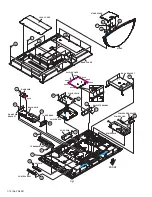
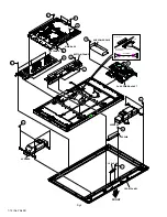
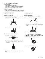
3.1.9 REMOVING THE SPEAKER (Fig.2)
• Remove the STAND.
• Remove the REAR COVER.
(1) Remove the 6 screws
[A]
.
(2) Remove the SPEAKER (L /R).
NOTE:
• Since the speaker is attached in a certain direction, attach
the speaker in the same correct direction as it has been
attached.
• When the speaker is decomposed, the performance cannot
be kept.
3.1.10 REMOVING THE LED PWB (Fig.2)
• Remove the STAND.
• Remove the REAR COVER.
(1) Remove the 2 screws
[B]
.
(2) Remove the LED PWB.
3.1.11 REMOVING THE LED LENS (Fig.2)
• Remove the STAND.
• Remove the REAR COVER.
• Remove the LED PWB.
(1) Remove the 2 screws
[C]
.
(2) Remove the LED LENS.
3.1.12 REMOVING THE SUB POWER PWB (Fig.2)
• Remove the STAND.
• Remove the REAR COVER.
(1) Remove the 4 screws
[D]
.
(2) Remove the SUB POWER PWB.
3.1.13 REMOVING THE LCD PANEL UNIT (Fig.2)
• Remove the STAND.
• Remove the REAR COVER.
• Remove the BACK BRACKET.
(1) Remove the 8 screws
[E]
.
(2) Remove the MAIN BASE.
(3) Remove the 3 screws
[F]
and 2 screw
[G]
.
(4) Remove the TOP FARAME.
(5) Remove the 2 screws
[H]
and 2 screw
[J]
.
(6) Remove the BOTTOM FARAME.
(7) Remove the LCD PANEL UNIT from the FRONT PANEL.
(8) Remove the 2 screws
[K]
.
(9) Remove the CARD PWB BRACKET from the LCD PANEL
UNIT.


