background image

2-26(No.YA711<Rev.001>)

(No.YA711<Rev.001>)2-25

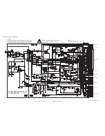
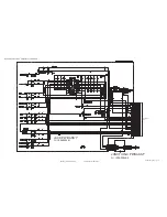
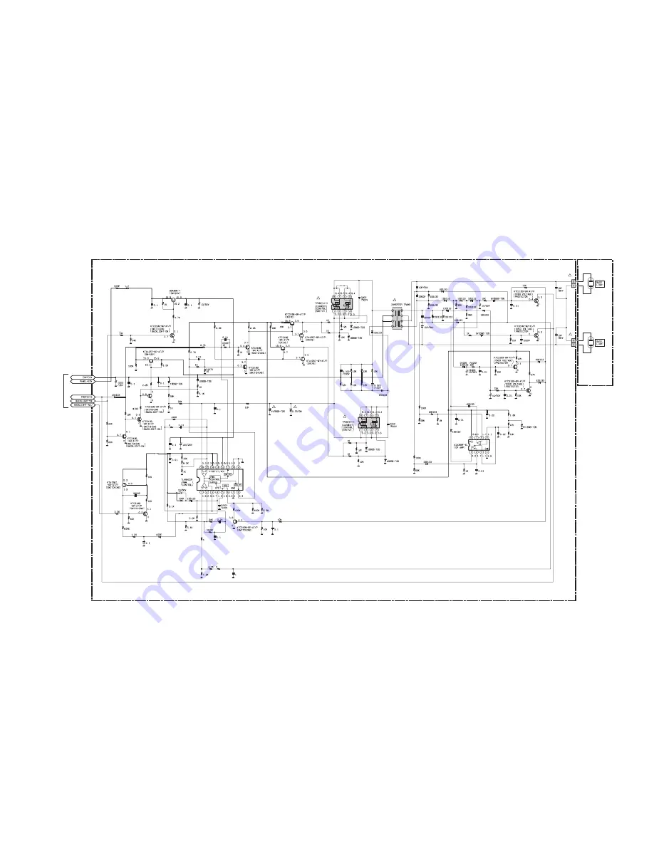
MAIN PWB ASS'Y(1/4)

FU-1ESA21430

LCD PANEL 
UNIT

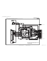
MAIN PWB(4/4)

A94N5SCM1_0430_1/4_0.0

!

!

!

!

!

!

!

R1117

R1004

R1005

R1074

R1026

C1011

C1018

C1038

D1016

D1021

D1018

R1028

R1027

R1030

Q1016

Q1007

Q1010

C1034

C1026

D1028

R1032

R1039

R1024

R1035

R1100

R1038

R1037

C1025

C1054

C1024

JS1005

R1107

R1110

R1044

R1109

R1043

R1052 D1045

C1031

C1028

C1056

R1046

R1056

Q1014

R1055

R1058

C1044

R1054

R1059

R1045

R1112

R1071 R1072

R1073

C1037

JS1007

R1105

R1106

D1038

R1108

R1095

C1016

C1027

C1045

Q1023

Q1024

R1036

R1040

R1041

IC1001

C1053

R1049

R1042

R1048

R1025

R1066

R1069

R1070

C1035

R1065

R1001

R1003

R1002

R1006

Q1001

Q1017

R1101

R1102

R1008

D1029

D1039

C1019

C1006

C1007

D1014

D1015

D1007

D1027

D1026

D1011

D1034

R1020

C1010

D1009

R1018

R1015

R1084

R1012

R1014

R1023

R1061

C1003

C1009

D1006

D1023

D1024

D1020

C1039

C1042

R1029

R1083

R1081

R1086

R1087

R1082

D1002

C1002

C1005

R1013

R1093

R1094

R1091

R1017

R1092

D1022

D1025

R1088

R1089

R1090

IC1002

C1041

C1043

D1040

C1012

D1030

R1104

R1011

R1103

R1010

Q1022

R1022

R1060

C1033

C1032

C1040

R1111

R1019

D1036

D1005

Q1003

Q1019

Q1009

Q1015

C1004

C1014

CN1002

CN1001

C1015

D1001

D1004

D1008

C1001

C1008

D1010

D1013

D1012

T1002

D1003

JS1013

R1007

Q1018

Q1005

JS1010

R1068

R1118

R1099

R1031

C1020

C1052

C1023

Q1011

Q1002

Q1006

Q1008

Q1012

Q1004

CIRCUIT DIAGRAMS 

MAIN PWB CIRCUIT DIAGRAM (1/4) 

Summary of Contents for LT19D200 - 19" LCD TV

Page 1: ...E OF CONTENTS 1 PRECAUTION 1 3 2 SPECIFIC SERVICE INSTRUCTIONS 1 5 3 DISASSEMBLY 1 8 4 ADJUSTMENT 1 14 5 TROUBLESHOOTING 1 19 MODEL NO RATING LABEL REAR AK VERSION LT 19D200 MODEL NAME There may be multiple versions of this TV model The TV version is identified by the letters next to the model number on the TV s Rating See illustration Use the service manual that matches the version of the TV HIGH...

Page 2: ...patibility DVD video DVD RW R DVD RW R audio CD video CD CD RW R Frequency response DVD linear sound 20 Hz to 20 kHz sample rate 48 kHz 20 Hz to 44 kHz sample rate 96 kHz CD 20 Hz to 20 kHz Signal to noise ratio S N ratio CD 90 dB JEITA Total distortion factor DVD 1 KHz 0 007 JEITA CD 1 KHz 0 007 JEITA Antenna Terminal VHF UHF ATSC DIGITAL CABLE IN F type connector 75Ω unbalanced coaxial 1 Video A...

Page 3: ...onents that indicate evidence of overheating should be replaced Always use the manufacturer s replacement components 6 Isolation Check Safety for Electrical Shock Hazard After re assembling the product always perform an isolation check on the exposed metal parts of the cabinet antenna terminals video audio input and output terminals Control knobs metal cabinet screw heads earphone jack control sha...

Page 4: ...st 30 cm away from the pickup lens when the diode is turned on Do not look directly at the laser beam CAUTION Use of controls and adjustments or doing procedures other than those specified herein may result in hazardous radiation exposure Do not look directly at the laser beam coming from the pickup or allow it to strike against your skin Location Top of LCD module Drive Mechanism Assembly Laser B...

Page 5: ...y hot air to the Flat Pack IC about 5 to 6 seconds Fig 2 1 Fig 2 1 2 Remove the flat pack IC with tweezers while applying the hot air 3 Bottom of the flat pack IC is fixed with glue to the PWB when removing entire flat pack IC first apply soldering iron to center of the flat pack IC and heat up Then remove glue will be melted Fig 2 6 4 Release the flat pack IC from the PWB using tweezers Fig 2 6 C...

Page 6: ...x which is applied to all pins of the flat pack IC you can remove it easily Fig 2 3 2 Affix the wire to a workbench or solid mounting point as shown in Fig 2 5 3 While heating the pins using a fine tip soldering iron or hot air blower pull up the wire as the solder melts so as to lift the IC leads from the PWB contact pads as shown in Fig 2 5 4 Bottom of the flat pack IC is fixed with glue to the ...

Page 7: ...semi conductors may occur due to a potential difference caused by electrostatic charge during unpacking or repair work 2 1 5 1 Ground for Human Body Be sure to wear a grounding band 1MΩ that is properly grounded to remove any static electricity that may be charged on the body 2 1 5 2 Ground for Workbench Be sure to place a conductive sheet or copper plate with proper grounding 1MΩ on the workbench...

Page 8: ... No Part Removal Fig No Remove Unhook Unlock Release Unplug Unclamp Desolder Note 1 Stand Assembly D1 3 S 1 2 Rear Cabinet D1 10 S 2 2 S 3 S 4 3 DVD Holder D2 D5 4 S 5 3 S 6 CN901 CN902 4 DVD Mechanism D2 D5 S 7 CN201 CN301 CN801 1 2 3 4 5 6 5 DVD Main PWB Unit D2 6 Jack Holder D D3 S 8 7 Digital Main PWB U nit D3 D5 4 S 9 S 10 4 S 11 2 H 1 CN301 CN302 CN303 CN3902 Shield Box 8 Jack Holder A D3 S ...

Page 9: ... remove the Chassis Cover remove two screws A as shown in Fig D2 b To avoid damage of the pickup unit laser diode confirm that the three short lands either of two places are shorted out by soldering between them as shown in View A in Fig D2 c Connect the FFC cables of the new DVD Mecha nism to the three connectors CN201 CN301 CN801 on the DVD Main PWB Unit d After confirming that the FFC cables ar...

Page 10: ...1 10 No YA711 Rev 002 2 Rear Cabinet S 1 1 Stand Assembly S 2 S 4 S 2 S 2 S 3 Fig D1 ...

Page 11: ...ws A then short the three short lands by soldering as shown in View for A View for A Either of two places FPC Cable Chassis Cover Pin A A Hole A Main Chassis Screws A S 5 S 7 S 6 S 6 A 5 DVD Main PWB unit 4 DVD Mechanism 3 DVD Holder Fig D2 ...

Page 12: ...1 12 No YA711 Rev 002 S 8 S 9 S 9 9 Jack PWB 6 Jack Holder D 8 Jack Holder A 10 Main PWB 7 Digital Main PWB Unit S 14 S 11 S 14 S 12 Shield Box S 13 H 1 S 10 Fig D3 ...

Page 13: ...1 13 S 16 S 18 S 17 S 17 12 LCD Module Assembly 11 Stand Holder 18 Function CBA 13 Speaker Holder 13 Speaker Holder 15 Junction C CBA 16 Junction B CBA 17 Junction A CBA 14 Speaker 19 Front Cabinet S 15 14 Speaker Fig D4 ...

Page 14: ...tached remote control unit as shown in Fig 1 4 4 HOW TO SET UP THE SERVICE MODE Service mode 1 Use the service remote control unit 2 Turn the power on 3 Press the service button on the service remote control unit The following screen appears 4 5 PURITY CHECK MODE This mode cycles through full screen displays of red green blue and white to check for non active pixels 1 Enter the Service mode 2 Each...

Page 15: ...l receptor must be set perpendicularly to the LCD Panel surface 4 Enter the Service mode Press VOLUME DOWN button on the service remote control unit and select C D mode 5 CUTOFF Press 1 button to select COR for Red Cutoff adjustment Press 3 button to select COB for Blue Cutoff adjustment DRIVE Press 4 button to select DR for Red Drive adjustment Press 6 button to select DB for Blue Drive adjustmen...

Page 16: ...mote control unit 4 To put the LCD TV DVD into the Flash clear mode press INPUT SELECT buttons on the remote control unit in that order within five seconds The following screen appears When OK appears on the screen the factory default will be set 5 To exit this mode press CHANNEL UP DOWN button to go to TV mode or press POWER button to turn the power off 4 8 2 LCD TV SECTION 1 Turn the power on 2 ...

Page 17: ...D mode again 9 Press 1 2 3 4 and INFO buttons on the remote control unit in that order Fig d appears on the screen 10 Press CLEAR button on the remote control unit Fig e ap pears on the screen When OK appears on the screen the factory default will be set Then the firmware renewal mode is complete 11 To exit this mode press CHANNEL UP DOWN button to go to TV mode or press POWER button to turn the p...

Page 18: ...dly remove the USB memory from the USB port Plug the AC cord in the wall outlet again and turn the power on NOTE When the Factory Upgrade is used after restarting TV shift to initial screen menu in service mode INITIAL IZED will appear on the upper right of the screen INI TIALIZED color will change to green from red when initializing is complete User Upgrade Upgrade the firmware only The setting v...

Page 19: ...rcuit of secondary side and service it if defective After servicing replace the fuse When the output voltage fluctuates FLOW CHART NO 3 Does the photocoupler circuit on the secondary side operate normally No Yes Check IC601 D633 Q631 and their periphery circuit and service it if defective When buzz sound can be heard in the vicinity of power circuit FLOW CHART NO 4 Check if there is any short circ...

Page 20: ...lector of Q201 Yes Check C631 D631 D668 and their periphery circuit and service it if defective P ON 7V is not output FLOW CHART NO 8 Is approximately 7V voltage supplied to the cathode of D641 Check C641 D641 and their periphery circuit and service it if defective Yes No Check if there is any leak or short circuit on the loaded circuit and service it if defective See FLOW CHART No 8 P ON 5V is no...

Page 21: ...o Yes Yes Check C639 D639 and their periphery circuit and service it if defective Check Q638 Q639 P ON H2 line and their periphery circuit and service it if defective No No EV 3 3V is not output FLOW CHART NO 13 Is approximately 4 6V voltage supplied to the collector of Q903 Yes Replace Q640 Check Q903 D905 and their periphery circuit and service it if defective P ON 3V is not output FLOW CHART NO...

Page 22: ...it and service it if defective Check C640 D640 and their periphery circuit and service it if defective Is approximately 4V voltage supplied to Pin 3 of IC901 Yes No Check Q901 Q902 DVD MAIN PWR line and their periphery circuit and service it if defective No EV 1 2V is not output FLOW CHART NO 16 Is approximately 5V voltage supplied to the emitter of Q901 Yes Replace IC901 P ON 9V is not output PAN...

Page 23: ...pproximately 34V voltage supplied to the collector of Q634 Yes Replace IC631 Check C636 D636 D637 and their periphery circuit and service it if defective Check Q202 Q203 D204 P ON H1 line and their periphery circuit and service it if defective Replace Q206 Is approximately 8V voltage supplied to the base of Q206 Yes No No LCD 7 1V is not output FLOW CHART NO 19 Is approximately 9V voltage supplied...

Page 24: ...eplace Digital Main PWB Unit When pressing each switches SW104 SW109 SW951 SW953 do the voltage of Pin 29 of CN302 and Pin 2 of CN303 increase Yes The key operation is not functioning FLOW CHART NO 1 Are the contact point and installation state of the key switches SW104 SW109 SW951 SW953 normal Re install the switches SW104 SW109 SW951 SW953 correctly or replace the poor switch Check the switches ...

Page 25: ... Module Assembly Replace Digital Main PWB Unit or LCD Module Assembly Pin 6 S VIDEO C Pin 8 S VIDEO Y Picture does not appear normally Y Pb Pr input FLOW CHART NO 6 Are the video signal inputted to Pin 15 17 19 of CN302 Check the line between Pin 15 17 19 of CN302 and input terminals JK731 JK732 JK733 and service it if defective Yes No Replace Digital Main PWB Unit or LCD Module Assembly Pin 15 VI...

Page 26: ... of IC803 and service it if defective Are the audio L R signals outputted to Pin 1 7 of IC803 No Yes Replace IC803 No Check SP861 SP862 and their periphery circuit and service it if defective Are the audio L R signals inputted to Pin 1 9 of IC801 Yes Yes Yes Audio is not outputted normally Component Audio input FLOW CHART NO 2 Are the audio L R signals inputted to Pin 4 11 of IC771 Check the line ...

Page 27: ...f defective Are the audio L R signals outputted to Pin 1 7 of IC803 No Yes Replace IC803 No Check SP861 SP862 and their periphery circuit and service it if defective Are the audio L R signals inputted to Pin 1 9 of IC801 Yes Yes Yes Audio is not outputted normally HDMI Audio input FLOW CHART NO 4 Are the audio L R signals inputted to Pin 5 14 of IC771 Check the line between Pin 5 14 of IC771 and i...

Page 28: ...ed to Pin 4 6 of IC801 Check IC801 and their periphery circuit and service it if defective No Yes Are the audio L R signals inputted to Pin 6 8 of CN301 Replace Digital Main PWB Unit Check the line between Pin 1 7 of IC803 and Pin 1 9 of IC801 and service it if defective Are the audio L R signals inputted to Pin 3 5 of IC803 No Yes Check the line between Pin 6 8 of CN301 and Pin 3 5 of IC803 and s...

Page 29: ...e Capacitor MF R Metal Film Resistor MF CAP Metalized Film Capacitor MG R Metal Glazed Resistor MM CAP Metalized Mylar Capacitor MP R Metal Plate Resistor MP CAP Metalized Polystyrol Capacitor OM R Metal Oxide Film Resistor PP CAP Polypropylene Capacitor CMF R Coating Metal Film Resistor PS CAP Polystyrol Capacitor UNF R Non Flammable Resistor TF CAP Thin Film Capacitor CH V R Chip Variable Resist...

Page 30: ... P W BOARD ASS Y FU 1ESA20948 4 3 10 JUNCTION C P W BOARD ASS Y FU 1ESA20948 5 3 10 PACKING 3 11 PACKING PARTS LIST 3 12 USING P W BOARD REMOTE CONTROL UNIT P W B ASS Y name P W B ASS Y No LT 19D200 AK MAIN PWB P W B FU 1ESA21430 JACK PWB P W B FU 1ESA20948 1 FUNCTION PWB P W B FU 1ESA20948 2 JUNCTION A P W B FU 1ESA20948 3 JUNCTION B P W B FU 1ESA20948 4 JUNCTION C P W B FU 1ESA20948 5 DIGITAL MA...

Page 31: ... 3 FU GBJS3060 SCREW x15 L 4 FU GBHS3080 SCREW x7 L 6 FU GCJP3120 SCREW x3 L 8 FU 1EM420633A ASSEMBLED SCREW x4 L 9 FU FPH34100 SCREW M4x10 x4 L 11 FU 1EM422042 HEX SCREW x2 L 12 FU 1EM424392A ASSEMBLED SCREW x4 L 17 FU 1ESA19526 STAND SCREW KIT Inc PolyBag x3 LCD1 FU UH19MXA LCD MODULE SP1 FU DS16070XQ001 SPEAKER SP2 FU DS16070XQ001 SPEAKER WR 1 FU WX1A94N0 105 WIRE ASSEMBLY WR 2 FU WX1A94F0 101 ...

Page 32: ...1 Rev 001 EXPLODED VIEW A1 A5 L8 L4 See Electrical Parts List for parts with this mark L6 PB3 PB5 PB6 SP1 SP2 PB1 B8 A3 L13 B2 L12 L12 LCD1 L9 L1 L8 B8 L1 L3 PB4 B11 WR1 WR7 L13 WR5 WR8 WR6 WR2 WR4 1B1 WR3 A14 PB8 ...

Page 33: ... No YA711 Rev 001 3 5 L1 L9 B10 L1 L3 L3 AC601 A7 PB2 L6 L2 L2 B3 B3 L1 L17 B13 L13 B12 B14 L3 B7 2 L12 L3 L11 A4 L9 L3 L4 L4 L3 A10 L4 A8 B9 L13 A9 B1 R5 R8 R6 L1 WR2 1B1 A15 PB7 ...

Page 34: ...IODE D1016 FU QDTZ001SS133 SI DIODE D1018 FU NDTB010BST26 ZENER DIODE D1020 FU NDTB5R1BST26 ZENER DIODE D1021 FU NDTB015BST26 ZENER DIODE D1022 FU QDTZ001SS133 SI DIODE D1023 FU QDTZ001SS133 SI DIODE D1024 FU QDTZ001SS133 SI DIODE D1025 FU QDTZ001SS133 SI DIODE D1026 FU QDTZ001SS133 SI DIODE D1027 FU QDTZ001SS133 SI DIODE D1028 FU NDTB4R7BST26 ZENER DIODE D1029 FU NDTB016BST26 ZENER DIODE D1030 FU...

Page 35: ...TOR 0 1uF 50V C647 FU CE1AMAVSL101 E CAPACITOR 100uF 10V M Ref No Part No Part Name Description Local C648 FU CE1EMAVSL470 E CAPACITOR 47uF 25V M C649 FU CE1AMAVSL221 E CAPACITOR 220uF 10V M C650 FU CE1AMAVSL221 E CAPACITOR 220uF 10V M C652 FU CE0KMASDL102 E CAPACITOR 1000uF 6 3V M C653 FU CE1JMASDL220 E CAPACITOR 22uF 50V M C654 FU CE1CMASDL101 E CAPACITOR 100uF 16V M C655 FU CE1JMAVSL1R0 E CAPAC...

Page 36: ... MG RESISTOR 100kΩ 1 10W J R229 FU RCX4100T1001 C RESISTOR 10Ω 1 4W J R230 FU RRXAJR5Z0103 MG RESISTOR 10kΩ 1 10W J Ref No Part No Part Name Description Local R231 FU RRXAJR5Z0152 MG RESISTOR 1 5kΩ 1 10W J R232 FU RRXAJR5Z0153 MG RESISTOR 15kΩ 1 10W J R233 FU RRXAJR5Z0103 MG RESISTOR 10kΩ 1 10W J R234 FU RRXAJR5Z0102 MG RESISTOR 1kΩ 1 10W J R238 FU RRXAZR5Z0000 MG RESISTOR 0Ω 1 10W R239 FU RCX4151...

Page 37: ...29ER007 FFC CONNECTOR CN862A FU J322C04TG001 CONNECTOR CN901 FU JC96J26ER007 FFC CONNECTOR CN902 FU JC62G13UG026 CONNECTOR F601 FU PAGE20CW3402 FUSE 125V 4A FH601 FU XH01Z00LY002 FUSE HOLDER FH602 FU XH01Z00LY002 FUSE HOLDER Ref No Part No Part Name Description Local JS304 FU RRXAZR5Z0000 MG RESISTOR 0Ω 1 10W JS801 FU RRXAZR5Z0000 MG RESISTOR 0Ω 1 10W JS802 FU RRXAZR5Z0000 MG RESISTOR 0Ω 1 10W JS8...

Page 38: ... JK753 FU JXRL010YUQ13 JACK AUDIO L IN JK754 FU JYRL010YUQ05 JACK AUDIO R IN JK841 FU JXRJ010YUQ06 RCA JACK DIGITAL AUDIO OUT JK851 FU JYSL010YUQ03 JACK HEADPHONE JS701 FU RRXAZR5Z0000 MG RESISTOR 0Ω 1 10W Ref No Part No Part Name Description Local D103 FU NP4Z000L53HT LED STAND BY D104 FU NPQ3L1CHCBK2 LED POWER D950 FU NPWZ0LTL307Y LED DVD C103 FU CE1CMAVSL470 E CAPACITOR 47uF 16V M C104 FU CHD1J...

Page 39: ...11 Rev 001 3 11 PACKING S3 S1 Tape Packing Tape Packing Tape Packing Tape S2 S3 X1 Some Ref Numbers are not in sequence Refer to EXPLODED VIEW PARTS LIST X2 S4 X10 X14 S6 Stand Assembly X4 X3 FRONT FRONT Tape ...

Page 40: ...1EM023965 TOP CUSHION S 3 FU 1EM023966 BOTTOM CUSHION 2pcs in 1set S 4 FU 1EM323958 SET BAG S 6 FU 1EM425888 STAND BAG X 1 FU 0EM408420A POLY BAG X 2 FU 1EMN24939 INST BOOK French Spanish English X 3 FU NF902UD REMOTE CONTROL X 4 DRY BATTERY R6P AA X 10 FU 1EMN24179 REGISTRATION CARD X 14 WARRANTY CARD CANADA FU 1EMN24899 ...

Page 41: ...UILT IN DVD PLAYER LT 19D200 AK MODEL NO RATING LABEL REAR AK VERSION LT 19D200 MODEL NAME There may be multiple versions of this TV model The TV version is identified by the letters next to the model number on the TV s Rating See illustration Use the service manual that matches the version of the TV HIGH DEFINITION TELEVISION ...

Page 42: ...ype MM Metalized mylar capacitor PP Polypropylene capacitor MPP Metalized polypropylene capacitor MF Metalized film capacitor TF Thin film capacitor BP Bipolar electrolytic capacitor TAN Tantalum capacitor 3 Coils No unit Others µH As specified No indication Ceramic capacitor 2 Capacitors Capacitance value 1 or higher pF less than 1 µF Withstand voltage No indication DC50 V Others DC withstand vol...

Page 43: ... SIGNAL PROCESS BLOCK DIAGRAM 2 23 CIRCUIT DIAGRAMS 2 25 MAIN PWB CIRCUIT DIAGRAM 2 25 MAIN PWB CIRCUIT DIAGRAM 3 4 AND JUNCTION B CIRCUIT DIAGRAM 2 29 FUNCTION PWB CIRCUIT DIAGRAM AND JUNCTION A PWB CIRCUIT DIAGRAM 2 33 JACK AND JUNCTION C PWB CIRCUIT DIAGRAM 2 35 DIGITAL MAIN PWB CIRCUIT DIAGRAM 2 37 DVD MAIN PWB CIRCUIT DIAGRAM 2 47 PATTERN DIAGRAMS 2 53 MAIN PWB PATTERN 2 53 JACK PWB PATTERN 2...

Page 44: ...o YA711 Rev 001 2 3 USING P W BOARD P W B ASS Y name MAIN P W BOARD JACK P W BOARD FUNCTION P W BOARD JUNCTION A P W BOARD JUNCTION B P W BOARD JUNCTION C P W BOARD DIGITAL MAIN P W BOARD DVD MAIN P W BOARD FU 1ESA21430 FU 1ESA20948 1 FU 1ESA20948 2 FU 1ESA20948 3 FU 1ESA20948 4 FU 1ESA20948 5 FU 1ESA19805 Not supply individual parts of this PWB FU N7EX2KUP Not supply individual parts of this PWB ...

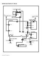
Page 45: ...02 CN3701 DIGITAL MAIN PWB UNIT CN102 CN101 CN101A CN702 AC CORD CN302 CN303 CN701 CN861A CN861B CL861 CN902 CN901 CN862A CN301 CN101B DVD MAIN PWB UNIT CN601 CN301 CN201 CN801 CN401 To DVD MECHANISM To LCD PANEL UNIT To Speaker To Speaker CN862B CL862 To LCD PANEL UNIT WIRING DIAGRAM TV CABLE 2 4 No YA711 Rev 001 ...

Page 46: ...V 10 EV 9V 11 EV 9V 12 GND 13 GND 14 GND 15 GND 16 GND 17 GND 18 GND 19 PWRCON NU 20 DVD SCLK 21 DVD CS 22 DVD DISC IN 23 CN901 CN862A JUNCTION C PWB 1 CL861 2 SP L SP GND SP861 SPEAKER L CH CN861B 1 1 SP L 2 2 SP L 3 3 SP GND 4 4 SP GND CN861A EV 1 2V 4 AL 3 3V 1 DVD SDATA 24 DVD REMOTE 25 DVD P ON 26 TO DVD MAIN CBA UNIT CN401 TO WIRING 2 2 DIAGRAM TO WIRING 2 2 DIAGRAM GND 7 GND 8 DVD Y 9 GND 1...

Page 47: ...P LOAD DISC 6 SL 5 SL 4 GND 3 SP 2 SP 1 FS 3 TS 4 GND CD PD 5 GND DVD PD 6 PD MONI 7 DVD LD 8 TS 1 FS 2 GND 11 NU 12 VREF 13 NU 14 B 15 C 16 GND LD 9 CD LD 10 A 17 D 18 CD DVD 19 DVD ON 5V 20 GND 10 GND 9 DVD Y 8 CN601 DVD AUDIO R 14 GND 11 DVD Pb 6 GND 5 DVD Pr 4 GND 7 DVD AUDIO L 12 DVD AUDIO MUTE 13 GND 15 DVD SPDIF 16 DISC IN CN5001 DISC OUT LED POWER 1 1 DVD DISC OUT 2 2 GND 4 4 DVD DISC IN 3...

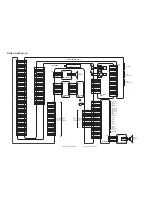
Page 48: ... EV 9V EV 1 2V LCD PANEL UNIT DVD MAIN PWB UNIT DIGITAL MAIN PWB UNIT PANEL 7 1V 8 P ON 3 3V 19 20 P ON 3 3V 6 7 PANEL 24 5V 4 PANEL 13V 2 3 AL 3 3V 21 22 16 10 P ON 7V 16 P ON 3V 10 P ON 5V 13 14 Q205 SW 24 5V Q901 Q902 SWITCHING 10 11 12 6 8 4 5 9 DVD ON 5V 10 EV 9V 11 12 1 AL 3 3V 1 EV 3 3V 6 8 EV 1 2V 4 5 DVD ON 3 3V 9 CN901 Q905 SW 9V VCOM 10 CAUTION Fixed voltage or Auto voltage selectable p...

Page 49: ...006 Q1008 Q1012 Q1002 Q1011 Q1023 Q1024 Q1022 DRIVE Q1010 Q1017 Q1018 DRIVE OSC PWM CONTROL LOGIC VCC DCT CURRENT CONTROL SWITCH CURRENT CONTROL SWITCH Q1009 OVER VOLTAGE PROTECTOR Q1015 OVER VOLTAGE PROTECTOR 11 8 5 6 15 3 4 VREF 14 12 16 2 1 SW 16V SW SW 16V Q1019 Q1003 LCD PANEL UNIT T1002 4 1 3 7 8 6 5 2 BACK LIGHT 1 2 CN1001 IC1002 COMPARATOR 6 7 5 2 3 1 PANEL 15V INV 31V INVERTER BLOCK DIAGR...

Page 50: ... DVD Pb DVD Y AA3 IF AGC HDMI IN1 HDMI IN2 JK3701 TMDS D0 TMDS D0 TMDS D1 TMDS D1 TMDS D2 TMDS D2 SDA SCL 7 9 4 6 1 3 10 12 16 15 7 9 4 6 1 3 10 12 16 15 JK3702 TMDS D0 TMDS D0 TMDS D1 TMDS D1 TMDS D2 TMDS D2 TMDS CLOCK TMDS CLOCK SDA SCL A9 B9 C8 C9 B8 A8 B10 A10 A11 B11 A5 B5 C4 C5 B4 A4 B6 A6 A7 B7 TMDS CLOCK TMDS CLOCK DEMODULATOR MPEG DECODER AE2 AF7 AUDIO I F TO AUDIO BLOCK DIAGRAM ACLK BCLK...

Page 51: ... 7 5 DRIVE CN601 CN902 DVD AUDIO L 5 9 DVD AUDIO R 3 11 DVD SPDIF 1 13 IC902 OP AMP 7 5 1 3 IC3801 D A CONVERTER D A CONVERTER 15 14 8 7 6 5 L CH R CH AUDIO L AUDIO R CN4001 CN303 DVD AUDIO L 24 24 DVD AUDIO R 26 26 DVD AUDIO L DVD AUDIO R TO DIGITAL SIGNAL PROCESS BLOCK DIAGRAM TO DIGITAL SIGNAL PROCESS BLOCK DIAGRAM INPUT1 DVD AUDIO L DVD AUDIO R DVD SPDIF LRCLK BCLK ADATA0 ACLK SHD SPDIF INPUT0...

Page 52: ... VIDEO Pr IN 16 16 MAIN PWB TU302 DIF OUT1 11 DIF OUT2 10 TUNER UNIT IF AGC 9 CN302 CN3702 DIF OUT1 26 26 IF AGC 24 24 DIF OUT2 28 28 TO DVD DIGITAL SIGNAL PROCESS BLOCK DIAGRAM DIF OUT1 DIF OUT2 IF AGC CN302 CN3702 VIDEO IN S VIDEO C IN S VIDEO Y IN S VIDEO SW COM VIDEO Y IN COM VIDEO Pr IN COM VIDEO Pb IN CN601 CN902 DVD MAIN PWB UNIT DVD Pb DVD Y 11 3 DVD Pb DVD Pr 13 1 DVD Pr 9 5 DVD Y CN4001 ...

Page 53: ... PWB UNIT CS WP SCK SIN SOUT CS WP KEY IN2 7 7 DVD LED 8 8 DVD SDATA U23 LED CONT DVD P ON DVD REMOTE DVD DISC IN DVD DISC OUT DVD AUDIO MUTE DVD SCLK DVD CS DVD SDATA DVD P ON DVD REMOTE DVD DISC IN DVD DISC OUT DVD AUDIO MUTE BUFFER IC201 Q207 Q208 Q209 DRIVE 6 6 DVD P ON 16 16 LED CONT 7 7 DVD REMOTE 8 8 DVD SDATA 13 13 DVD SCLK 11 11 DVD CS 9 9 DVD DISC IN 15 15 DVD DISC OUT 25 25 DVD AUDIO MU...

Page 54: ...1 17 18 23 6 4 5 3 1 2 25 24 27 26 121 SP ROT 124 FD OFST 123 TD OFST RESET IC461 2 1 3 3V TO DVD DIGITAL SIGNAL PROCESS BLOCK DIAGRAM DRIVE PWB DVD MAIN PWB UNIT 122 SL ADS DISC IN 1 2 6 7 5 3 3 DVD DISC IN 3 2 DVD DISC OUT 2 CN801 CN5001 DISC OUT SENSOR PWB 3 3V 1 LED POWER 1 Q804 63 DVD DISC IN 61 DVD DISC OUT TO SYSTEM CONTROL BLOCK DIAGRAM 53 DVD SCLK 54 DVD CS 49 DVD REMOTE 56 DVD SDATA DVD ...

Page 55: ...NTROLLER TIMER WATCH DOG TIMER REMOTE CONTROL 32BIT CPU STREAM I F EXTERNAL MEMORY I F SDRAM ECC UMAC 100 115 116 113 114 106 104 105 103 62 DEBUG BCU INST CACHE DATA CACHE D A 131 130 Y Pb DVD Y DVD Pb 152 DVD SPDIF 151 DVD AUDIO MUTE 146 DVD AUDIO R 144 DVD AUDIO L SDRAM ADDRESS 0 10 IC103 FLASH ROM FLASH ROM 29 36 38 45 FDQ 0 15 1 9 16 25 48 FADR 0 19 SDRAM DATA 0 15 PICKUP TO DVD SYSTEM CONTRO...

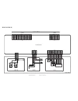
Page 56: ...25 R1066 R1069 R1070 C1035 R1065 R1001 R1003 R1002 R1006 Q1001 Q1017 R1101 R1102 R1008 D1029 D1039 C1019 C1006 C1007 D1014 D1015 D1007 D1027 D1026 D1011 D1034 R1020 C1010 D1009 R1018 R1015 R1084 R1012 R1014 R1023 R1061 C1003 C1009 D1006 D1023 D1024 D1020 C1039 C1042 R1029 R1083 R1081 R1086 R1087 R1082 D1002 C1002 C1005 R1013 R1093 R1094 R1091 R1017 R1092 D1022 D1025 R1088 R1089 R1090 IC1002 C1041 ...

Page 57: ... R907 BC901 Q907 Q906 C907 C928 C927 C925 C926 C924 L901 CN902 C922 C923 R940 R943 R942 R935 R936 R933 R904 R905 IC902 R941 R931 C906 C929 BC902 R908 C919 D906 Q904 R922 R919 C917 C914 C911 D907 R920 R909 CN303 D415 R921 R926 C918 C920 D905 R918 C309 TU302 R313 JS305 JS306 JS304 BC301 C304 L301 C301 R305 L303 C311 R679 D417 CN302 R303 R302 C310 R225 R226 R228 R229 Q207 Q208 R227 R238 IC201 R224 C2...

Page 58: ...N701 MAIN PWB 2 4 CN102 JS101 BC801 C802 C831 R811 R836 C827 C825 C830 C828 C829 C826 R830 R813 R814 R803 Q801 R819 R818 R817 R808 R809 R816 R815 CN862A CN862B CN702 C805 D808 D809 C807 C808 R805 R678 IC801 R804 C806 CL862 D804 R820 R842 C833 C813 C811 C812 C809 C816 R810 R409 R821 D414 D413 D805 C817 C810 R823 R826 C832 IC803 R838 R834 R837 R807 R806 MAIN PWB CIRCUIT DIAGRAM 3 4 AND JUNCTION B CI...

Page 59: ...651 D649 D650 D651 D654 D670 D657 D405 D412 D659 D411 D660 C647 C221 C220 C650 C649 C661 C652 C648 C218 C219 CN201 IC631 D655 D416 R413 R688 R689 R659 R682 R684 R685 R686 Q643 Q402 Q636 Q635 Q638 Q639 Q640 Q637 R683 R408 R406 R632 R633 R662 R661 R663 R664 R690 R690 R665 R666 R667 R670 R671 R673 R674 R699 R672 D208 D662 D410 D404 R668 R669 R660 R407 D207 C204 C656 C646 D205 D203 D206 C207 R223 R649...

Page 60: ... MAIN PWB 3 4 CN102 A94N5SCF_0430_1 1_0 0 R106 R107 R108 R109 R110 R111 R112 R113 R114 R953 R952 C108 C109 CN101B CN101A CN101 C951 R115 R118 R116 R956 R951 SW109 SW108 SW107 SW953 SW952 SW951 SW106 SW105 SW104 C104 C103 RS101 R950 D950 D103 D104 C107 FUNCTION PWB CIRCUIT DIAGRAM AND JUNCTION A PWB CIRCUIT DIAGRAM ...

Page 61: ...CL861 R797 C776 C775 Q771 Q722 Q773 Q774 R785 R786 R787 R781 R782 R783 R852 R851 L851 L853 L852 JK851 CN701 C771 C773 BC771 BC841 C843 Q841 R843 C845 C704 C703 C723 C724 C743 C744 C734 C735 C736 R718 R712 R711 JK711 JK721 JK722 JK741 JK742 JK731 JK732 JK733 JK751 JK752 JK753 JK754 R717 R727 R728 R721 R722 R741 R742 R731 C731 C732 C733 C751 C754 C755 C756 C757 C752 R732 R733 R751 R756 R757 R758 R75...

Page 62: ...matic Diagram Section 1 NOTE LCD PANEL UNIT C3901 C3903 R3932 R3909 R3913 R3934 R3916 R3902 C3912 C3911 L3907 CN3902 L3906 L3905 L3904 L3903 L3901 L3902 L3908 R3920 R3917 R3915 R3914 C3902 C3910 C3927 C3924 R3901 R3927 R3928 R3929 R3930 R3931 R3935 IC3901 R3936 C3921 IC3301 C3904 R3933 IC4202 DIGITAL MAIN PWB CIRCUIT DIAGRAM 1 5 This schematic is only for reference Avoid replacing individual parts...

Page 63: ...59 R3501 C3516 C3517 C3026 C3025 C3024 C3023 C3037 C3036 C3035 C3034 C3022 C3020 C3021 R3023 R3021 R3022 R3031 C3045 C3047 C3028 C3029 C3030 C3039 C3040 C3048 C3049 C3050 C3041 R3033 R3016 R3019 R3025 R3024 R3020 R3018 R3017 R3026 R3032 C3734 C3738 C3739 C3736 C3714 CN3702 R3703 R3718 R3719 R3717 R3735 R3737 R3721 R3027 R3034 D3706 R3035 R3036 R3038 R3037 R3732 R3733 D3703 R3028 R3029 R3722 C3740 ...

Page 64: ...ection 1 NOTE DIGITAL MAIN PWB 5 5 DIGITAL MAIN PWB 5 5 DIGITAL MAIN PWB 4 5 OPEN IC3301 C3055 C3056 C3057 C3058 R3041 R3803 IC3801 R3820 R3821 C3802 C3803 C3801 R3804 BC3801 R4101 R4102 R4105 R4104 R4106 R4103 R3155 R3809 R3808 R3802 R3813 R3801 R3810 R3811 R3814 R3156 R3150 CN4101 R3042 R3043 R3828 R3829 R3830 R3831 R3832 C3829 C3828 C3054 C3015 C3053 C3016 C3052 C3017 IC3303 IC3302 C3301 DIGITA...

Page 65: ...3730 D3701 R3729 R3725 C3110 R3124 R3116 R3117 R3114 R3115 R3119 R3120 R3113 R3742 R3407 R3408 R3772 C3743 R3779 C4101 C3742 JK3702 JK3701 R3726 C3744 C3745 R3776 Q3703 C3420 L3401 R3402 R3403 C3403 C3404 C3405 C3406 C3407 C3408 C3409 C3410 C3411 C3412 C3413 C3414 C3415 C3416 C3417 C3418 C3107 R3105 D3101 C3101 C3116 R3404 R3405 R3406 C3109 C3108 R3128 R3138 R3139 R3162 R3126 R3121 R3715 R3766 R37...

Page 66: ...C3595 C3641 C3594 C3593 C3592 C3590 C3589 C3588 C3587 C3586 C3103 C3508 C3504 R3505 R3103 C3503 C3032 C3033 C3031 L3502 L3501 C3114 C3104 C3570 C3569 C3568 C3543 C3542 C3541 C3539 C3538 C3537 C3536 C3534 C3533 C3532 C3531 C3529 C3528 C3527 C3526 IC3301 R3323 R3322 C3518 C3501 C3001 C3051 R3040 C3510 C3509 C3519 C3513 C3512 C3514 C3506 C3010 C3018 C3522 C3019 C3524 C3601 C3605 R3616 R3603 R3615 C36...

Page 67: ...301 C314 C301 C422 C423 C425 C426 C427 C411 C410 C416 L402 L403 R264 R269 R280 R279 R277 R284 R285 C288 C284 C280 C289 C281 R815 L201 C202 C210 C203 R261 C263 C259 C250 C257 C232 C253 C233 R322 C804 R818 R817 R806 R805 R803 R801 R811 R325 C802 C801 R816 R812 CN801 CN5001 CN301 Q804 IC201 C215 C317 R319 R320 C318 C310 R318 R317 C315 C316 C471 R471 C473 R411 R403 R406 R404 R407 R402 IC462 IC461 R251...

Page 68: ...C102 C103 C104 C105 C106 C107 C108 C109 C110 C111 C112 C113 C114 C115 C117 C119 C223 C226 C225 C231 C230 C222 C211 C214 C128 C130 C131 C136 C123 L108 C212 C328 C329 C116 R112 C120 C125 C623 C196 C195 C118 C192 C191 R191 R192 X101 C197 R195 R114 C122 R113 R128 C135 C134 C237 C239 R291 DVD MAIN PWB CIRCUIT DIAGRAM 2 3 This schematic is only for reference Avoid replacing individual parts Relpace the ...

Page 69: ...WB 1 3 DVD MAIN PWB 2 3 MAIN PWB 2 4 CN902 C501 C504 C513 L501 R567 R565 C561 R106 R611 R623 R624 R621 L104 L616 L614 L613 L612 L618 C610 C608 C620 C613 CN601 C612 C603 C604 R604 C625 C617 IC503 R510 IC103 C514 C505 C506 C502 C503 DVD MAIN PWB CIRCUIT DIAGRAM 3 3 This schematic is only for reference Avoid replacing individual parts Relpace the entire PWB ASS Y only ...

Page 70: ...2 54 No YA711 Rev 001 No YA711 Rev 001 2 53 TOP PATTERN DIAGRAMS MAIN PWB PATTERN SOLDER SIDE ...

Page 71: ... No YA711 Rev 001 2 55 2 56 No YA711 Rev 001 R699 TOP MAIN PWB PATTERN PARTS SIDE ...

Page 72: ...813 J819 R763 R756 CN871 C861 J802 J801 C776 R779 J820 R796 R777 R797 J822 C744 R736 C736 J818 J810 BC841 C842 R845 R847 R846 C843 C755 C754 C756 C751 C752 C703 C753 C757 C758 C704 C723 C724 R756 JK711 JK841 R758 R751 R753 R752 R795 R764 R787 R711 R717 R763 R786 R755 R754 R718 R792 R727 R721 R793 R722 R742 R733 R732 R780 R781 R782 R783 R772 R776 R778 Q774 Q773 C775 C771 C772 C851 JK851 JK754 JK722...

Page 73: ...f CN302 WF6 VIDEO Pb VIDEO Pb 0 2V 0 2V 20 20µs Pin 17 of CN302 WF5 VIDEO Y VIDEO Y 0 2V 0 2V 20 20µs Pin 15 of CN302 WF4 WAVEFORMS Input NTSC Color Bar Signal with 1kHz Audio Signal DVD Video Play MODE WF8 WF13 Waveforms to be observed at Waveform check points Shown in Schematic Diagram WF8 Pin 9 of CN902 WF9 Pin 11 of CN902 WF11 Pin 5 of CN902 Pin 1 of CN902 WF13 Pin 3 of CN902 WF12 20 20µs 0 5V...

Page 74: ... No YA711 Rev 001 Display Division 12 3 chome Moriya cho Kanagawa ku Yokohama city Kanagawa prefecture 221 8528 Japan Victor Company of Japan Limited VSE Printed in Japan ...

Reviews: