background image

LX-D1010G

No. PA012

Feb.2000

COPYRIGHT © 2000 VICTOR COMPANY OF JAPAN, LTD.

LX-D1010G

CONTENTS

„


SPECIFICATIONS

・・・・・・・・

・・・・・・・・

・・・・・・・・

・・・・・・・・・

・・

・・・・・・・・・・・・・・・・・・・・・

・・・・・・・・・・・・・・・・・・・・

・・・・・・・・・・・・・・・・・・・・

・・・・・・・・・・・・・・・・・・・・・

・・

・・・

・・

・・

・・ ・・・・・・・・

・・・・・・・・

・・・・・・・・

・・・・・・・・・

・・

・・・・・・・・・・・・・・・・・・・・・

・・・・・・・・・・・・・・・・・・・・

・・・・・・・・・・・・・・・・・・・・

・・・・・・・・・・・・・・・・・・・・・

・・

Table-2

„


SAFETY PRECAUTIONS

・・・・・・・・

・・・・・・・・

・・・・・・・・

・・・・・・・・・

・・

・・・・・・・・・・・・・・・・・・・・・

・・・・・・・・・・・・・・・・・・・・

・・・・・・・・・・・・・・・・・・・・

・・・・・・・・・・・・・・・・・・・・・

・・

・・・

・・

・・

・・ ・・・・・・・・

・・・・・・・・

・・・・・・・・

・・・・・・・・・

・・

・・・・・・・・・・・・・・・・

・・・・・・・・・・・・・・・

・・・・・・・・・・・・・・・

・・・・・・・・・・・・・・・

I

„


INSTRUCTION MANUAL

・・・・・・・・

・・・・・・・・

・・・・・・・・

・・・・・・・・・

・・

・・・・・・・・・・・・・・・・・・・・・

・・・・・・・・・・・・・・・・・・・・

・・・・・・・・・・・・・・・・・・・・

・・・・・・・・・・・・・・・・・・・・・

・・

・・・

・・

・・

・・ ・・・・・・・・

・・・・・・・・

・・・・・・・・

・・・・・・・・・

・・

・・・・・・・・・・・・・・・・・

・・・・・・・・・・・・・・・・

・・・・・・・・・・・・・・・・

・・・・・・・・・・・・・・・・

„


1. Field Service

・・・・・・・・

・・・・・・・・

・・・・・・・・

・・・・・・・・・

・・

・・・・・・・・・・・・・・・・・・・・・

・・・・・・・・・・・・・・・・・・・・

・・・・・・・・・・・・・・・・・・・・

・・・・・・・・・・・・・・・・・・・・・

・・

・・・

・・

・・

・・ ・・・・・・・・

・・・・・・・・

・・・・・・・・

・・・・・・・・・

・・

・・・・・・・・・・・・・・・・・・・・・

・・・・・・・・・・・・・・・・・・・・

・・・・・・・・・・・・・・・・・・・・

・・・・・・・・・・・・・・・・・・・・・

・・

・・・

・・

・・

・・

1-1

„


2. Packing Method

・・・・・・・・

・・・・・・・・

・・・・・・・・

・・・・・・・・・

・・

・・・・・・・・・・・・・・・・・・・・・

・・・・・・・・・・・・・・・・・・・・

・・・・・・・・・・・・・・・・・・・・

・・・・・・・・・・・・・・・・・・・・・

・・

・・・

・・

・・

・・ ・・・・・・・・

・・・・・・・・

・・・・・・・・

・・・・・・・・・

・・

・・・・・・・・・・・・・・・・・・・・・

・・・・・・・・・・・・・・・・・・・・

・・・・・・・・・・・・・・・・・・・・

・・・・・・・・・・・・・・・・・・・・

2-1

„


3. Before Disassembling

・・・・・・・・

・・・・・・・・

・・・・・・・・

・・・・・・・・・

・・

・・・・・・・・・・・・・・・・・・・・・

・・・・・・・・・・・・・・・・・・・・

・・・・・・・・・・・・・・・・・・・・

・・・・・・・・・・・・・・・・・・・・・

・・

・・・

・・

・・

・・ ・・・・・・・・

・・・・・・・・

・・・・・・・・

・・・・・・・・・

・・

・・・・・・・・・・・・・・・・

・・・・・・・・・・・・・・・

・・・・・・・・・・・・・・・

・・・・・・・・・・・・・・・

3-1

„


4. Removing Major Parts

・・・・・・・・

・・・・・・・・

・・・・・・・・

・・・・・・・・・

・・

・・・・・・・・・・・・・・・・・・・・・

・・・・・・・・・・・・・・・・・・・・

・・・・・・・・・・・・・・・・・・・・

・・・・・・・・・・・・・・・・・・・・・

・・

・・・

・・

・・

・・ ・・・・・・・・

・・・・・・・・

・・・・・・・・

・・・・・・・・・

・・

・・・・・・・・・・・・・・・・

・・・・・・・・・・・・・・・

・・・・・・・・・・・・・・・

・・・・・・・・・・・・・・・

4-1

„


5. Hyper Terminal Setting Method

・・・・・・・・

・・・・・・・・

・・・・・・・・

・・・・・・・・・

・・

・・・・・・・・・・・・・・・・・・・・・

・・・・・・・・・・・・・・・・・・・・

・・・・・・・・・・・・・・・・・・・・

・・・・・・・・・・・・・・・・・・・・・

・・

・・・

・・

・・

・・ ・・・・・・・・

・・・・・・・・

・・・・・・・・

・・・・・・・・・

・・

・・・・・・・・・

・・・・・・・・

・・・・・・・・

・・・・・・・・

5-1

„


6. Personal Computer Connection Method

・・・・・・・・

・・・・・・・・

・・・・・・・・

・・・・・・・・・

・・

・・・・・・・・・・・・・・・・・・・・・

・・・・・・・・・・・・・・・・・・・・

・・・・・・・・・・・・・・・・・・・・

・・・・・・・・・・・・・・・・・・・・・

・・

・・・

・・

・・

・・ ・・・・・・・・

・・・・・・・・

・・・・・・・・

・・・・・・・・・

・・

6-1

„


7. Circuit Adjustment Method

・・・・・・・・

・・・・・・・・

・・・・・・・・

・・・・・・・・・

・・

・・・・・・・・・・・・・・・・・・・・・

・・・・・・・・・・・・・・・・・・・・

・・・・・・・・・・・・・・・・・・・・

・・・・・・・・・・・・・・・・・・・・・

・・

・・・

・・

・・

・・ ・・・・・・・・

・・・・・・・・

・・・・・・・・

・・・・・・・・・

・・

・・・・・・・・・・・・

・・・・・・・・・・・

・・・・・・・・・・・

・・・・・・・・・・・

7-1

„


8. About Hidden Commands

・・・・・・・・

・・・・・・・・

・・・・・・・・

・・・・・・・・・

・・

・・・・・・・・・・・・・・・・・・・・・

・・・・・・・・・・・・・・・・・・・・

・・・・・・・・・・・・・・・・・・・・

・・・・・・・・・・・・・・・・・・・・・

・・

・・・

・・

・・

・・ ・・・・・・・・

・・・・・・・・

・・・・・・・・

・・・・・・・・・

・・

・・・・・・・・・・・・・

・・・・・・・・・・・・

・・・・・・・・・・・・

・・・・・・・・・・・・

8-1

„


9. When replacement of the Main PWB Ass’y is necessary

・・・・・・・・

・・・・・・・・

・・・・・・・・

・・・・・・・・・

・・

・・・・・・・・・・・・・・・・・・・・

・・・・・・・・・・・・・・・・・・・

・・・・・・・・・・・・・・・・・・・

・・・・・・・・・・・・・・・・・・・

9-1

„


10. Using the Warning Acquisition Software

・・・・・・・・

・・・・・・・・

・・・・・・・・

・・・・・・・・・

・・

・・・・・・・・・・・・・・・・・・・・・

・・・・・・・・・・・・・・・・・・・・

・・・・・・・・・・・・・・・・・・・・

・・・・・・・・・・・・・・・・・・・・・

・・

・・・

・・

・・

・・ ・・・・・・・・

・・・・・・・・

・・・・・・・・

・・・・・・・・

10-1

„


11. About Indicator Error Displays

・・・・・・・・

・・・・・・・・

・・・・・・・・

・・・・・・・・・

・・

・・・・・・・・・・・・・・・・・・・・・

・・・・・・・・・・・・・・・・・・・・

・・・・・・・・・・・・・・・・・・・・

・・・・・・・・・・・・・・・・・・・・・

・・

・・・

・・

・・

・・ ・・・・・・・・

・・・・・・・・

・・・・・・・・

・・・・・・・・・

・・

・・・・・・・・

・・・・・・・

・・・・・・・

・・・・・・・

11-1

„


12. Entry

・・・・・・・・

・・・・・・・・

・・・・・・・・

・・・・・・・・・

・・

・・・・・・・・・・・・・・・・・・・・・

・・・・・・・・・・・・・・・・・・・・

・・・・・・・・・・・・・・・・・・・・

・・・・・・・・・・・・・・・・・・・・・

・・

・・・

・・

・・

・・ ・・・・・・・・

・・・・・・・・

・・・・・・・・

・・・・・・・・・

・・

・・・・・・・・・・・・・・・・・・・・・

・・・・・・・・・・・・・・・・・・・・

・・・・・・・・・・・・・・・・・・・・

・・・・・・・・・・・・・・・・・・・・・

・・

・・・

・・

・・

・・ ・・・・・・

・・・・・・

・・・・・・

・・・・・・

12-1

„


13. Lead Wire Wiring Diagram

・・・・・・・・

・・・・・・・・

・・・・・・・・

・・・・・・・・・

・・

・・・・・・・・・・・・・・・・・・・・・

・・・・・・・・・・・・・・・・・・・・

・・・・・・・・・・・・・・・・・・・・

・・・・・・・・・・・・・・・・・・・・・

・・

・・・

・・

・・

・・ ・・・・・・・・

・・・・・・・・

・・・・・・・・

・・・・・・・・・

・・

・・・・・・・・・・・・

・・・・・・・・・・・

・・・・・・・・・・・

・・・・・・・・・・・

13-1

„


14. Connector Terminal Functions

・・・・・・・・

・・・・・・・・

・・・・・・・・

・・・・・・・・・

・・

・・・・・・・・・・・・・・・・・・・・・

・・・・・・・・・・・・・・・・・・・・

・・・・・・・・・・・・・・・・・・・・

・・・・・・・・・・・・・・・・・・・・・

・・

・・・

・・

・・

・・ ・・・・・・・・

・・・・・・・・

・・・・・・・・

・・・・・・・・・

・・

・・・・・・・・

・・・・・・・

・・・・・・・

・・・・・・・

14-1

„


15. Block Diagrams

・・・・・・・・

・・・・・・・・

・・・・・・・・

・・・・・・・・・

・・

・・・・・・・・・・・・・・・・・・・・・

・・・・・・・・・・・・・・・・・・・・

・・・・・・・・・・・・・・・・・・・・

・・・・・・・・・・・・・・・・・・・・・

・・

・・・

・・

・・

・・ ・・・・・・・・

・・・・・・・・

・・・・・・・・

・・・・・・・・・

・・

・・・・・・・・・・・・・・・・・・・・・

・・・・・・・・・・・・・・・・・・・・

・・・・・・・・・・・・・・・・・・・・

・・・・・・・・・・・・・・・・・・・・

15-1

„


16. Overall Connection Diagrams

・・・・・・・・

・・・・・・・・

・・・・・・・・

・・・・・・・・・

・・

・・・・・・・・・・・・・・・・・・・・・

・・・・・・・・・・・・・・・・・・・・

・・・・・・・・・・・・・・・・・・・・

・・・・・・・・・・・・・・・・・・・・・

・・

・・・

・・

・・

・・ ・・・・・・・・

・・・・・・・・

・・・・・・・・

・・・・・・・・・

・・

・・・・・・・・・

・・・・・・・・

・・・・・・・・

・・・・・・・・

16-1

„


PARTS LIST

・・・・・・・・

・・・・・・・・

・・・・・・・・

・・・・・・・・・

・・

・・・・・・・・・・・・・・・・・・・・・

・・・・・・・・・・・・・・・・・・・・

・・・・・・・・・・・・・・・・・・・・

・・・・・・・・・・・・・・・・・・・・・

・・

・・・

・・

・・

・・ ・・・・・・・・

・・・・・・・・

・・・・・・・・

・・・・・・・・・

・・

・・・・・・・・・・・・・・・・・・・・・

・・・・・・・・・・・・・・・・・・・・

・・・・・・・・・・・・・・・・・・・・

・・・・・・・・・・・・・・・・・・・・・

・・

・・・

・・

・・

・・ ・・・

・・・

・・・

・・・

Parts-1

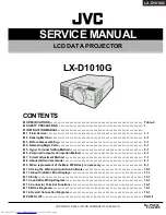
SERVICE MANUAL

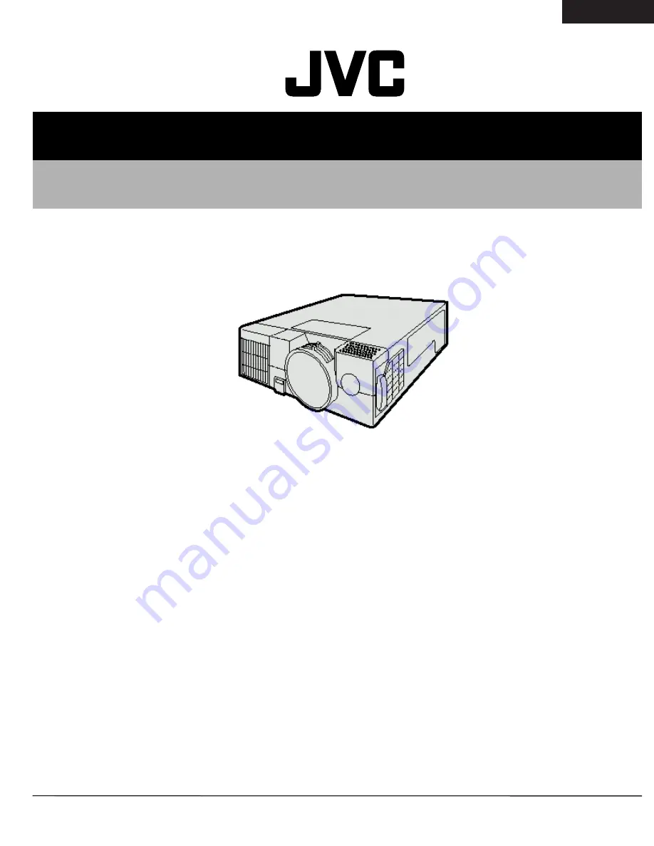
LCD DATA PROJECTOR

Summary of Contents for LX-D1010G - Lcd Projector

Page 1: ...al Setting Method 5 1 6 Personal Computer Connection Method 6 1 7 Circuit Adjustment Method 7 1 8 About Hidden Commands 8 1 9 When replacement of the Main PWB Ass y is necessary 9 1 10 Using the Warning Acquisition Software 10 1 11 About Indicator Error Displays 11 1 12 Entry 12 1 13 Lead Wire Wiring Diagram 13 1 14 Connector Terminal Functions 14 1 15 Block Diagrams 15 1 16 Overall Connection Dia...

Page 2: ...e 40 300 inch aspect ratio 4 3 Light source lamp 150 W UHP ELECTRIC Video compatibility NTSC NTSC 4 43 PAL including PAL M N SECAM PAL 60 DVD Component HDTV 1080i 720p 525p PC compatibility Resolution 640 400 1024 768 Compressed 1280 1024 Sync on Green available Speaker 6 cm square type 8W 1W CONTROL CONNECTORS RS 232C Serial DIN 8 pin female connector USB terminal for Mouse INPUT CONNECTORS S vid...

Page 3: ...acity should be inserted between the product and the AC power supply point while performing any service on some products when the HOT chassis is exposed 5 Don t short between the LIVE side ground and ISOLATED side ground or EARTH side ground when repairing Some model s power circuit is partly different in the GND The difference of the GND is shown by the LIVE side GND the ISOLATED side GND and EAR...

Page 4: ...N High Temperature Do not replace the lamp for 1hour after power off Turn off power before opening this lamp cover See user s manual for Replacing the Lamp Replace with same type lamp rated Lamp Cover CAUTION High brightness Do not look into the lens during operation Lens Cap CAUTION Laser Radiation LASER RADIATION DO NOT STARE INTO BEAM WAVE LENGTH 640 660nm MAX OUTPUT 1mW CLASS 2 LASER PRODUCT I...

Page 5: ... Video Projector complies with the requirements of the EC Directive 89 336 EEC EMC Directive as amended by Directive 93 68 EEC and 73 23 EEC Low Voltage Directive as amended by Directive 93 68 EEC The electro magnetic susceptibility has been chosen at a level that gains proper operation in residential areas on business and light industrial premises and on small scale enterprises inside as well as ...

Page 6: ...ilation ensuring reliable operation of the projector and to protect it from overheating Do not block these openings or allow them to be blocked by placing the projector on a bed sofa rug or bookcase Ensure that there is adequate ventilation and that the manufacturer s instruc tions have been adhered to EN 5 ENGLISH WARNING Unplug immediately if there is something wrong with your projector Do not o...

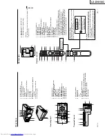
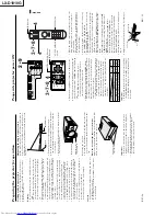
Page 7: ... HIDE COMPUTER VIDEO MOUSE LASER MENU ENTER R CLICK AUTO POSITION STILL P in P EXPAND VOLUME 18 Remote control 1 Transmitter indicator 2 POWER button 3 COMPUTER button 4 MOUSE button 5 Right click button For mouse 6 MENU button 7 AUTO POSITION button 8 PinP button 9 VOLUME buttons 10 EXPAND button 11 STILL button 12 ENTER button 13 Mouse pointer Direction button 14 LASER button 15 VIDEO button 16 ...

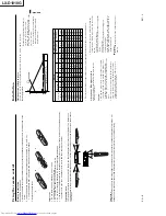
Page 8: ...or recommended distances in maximum zoom and minimum zoom Ceiling mount Rear projection Ask a specialist for installation For more details consult your dealer Caution Placing the projector on a carpet reduces ventila tion from the fan at the bottom and might cause problems Place a hard board or similar item under the projector to facilitate ventilation of the unit Place the projector more than 50 ...

Page 9: ...depending on the connected equipment Use mini D SUB 15 pin BNC conversion cable for connection Some DVD players may not project the image correctly When connecting with HDTV equipment which has R G B output set RGB for the COMPUTER INPUT in the SIGNAL setting menu Change the setting in the SIGNAL menu when 525p signal is inputted Refer to page 20 B G R C B P B Y C R P R HD CS VD DVD player or HDTV...

Page 10: ...mpatible with screen size chart on page 9 Note the distance from the screen chart Adjustment foot up and down Release button Adjustment foot right and left EN 13 ENGLISH To operate projector power ON When the lamp indicator is blinking red the the lamp should be replaced Replace the lamp See pages 23 and 26 The picture might not be of optimum performance in extreme hot or cold conditions The proje...

Page 11: ...After the lamp is turned off the lamp cannot be switched on again for 60 seconds as a precaution ary measure It will take another 60 seconds before the lamp indicator goes off If you wish to turn on the projector again wait until the indicator is off then press the POWER button The exhaust fan rotates faster when the tempera ture around the projector rises When the temperature around the projector...

Page 12: ...ch are recorded as squeezed images in right and left direction LANGUAGE Use to select the language for the projector display such as menu 日本語 English Español Deutsch Français Italiano 中文 Opt CONTRAST IMAGE 0 BRIGHTNESS 0 COLOR TEMP STANDARD TINT 0 COLOR 0 SHARPNESS 0 XGA60 COLOR MATRIX USER Menu operation continued EN 17 ENGLISH 4 SIGNAL MEMORY CALL Use to select AUTO USER 1 or USER 2 See below HO...

Page 13: ...or 7 Repeat steps 5 and 6 for more adjusting 8 Exit the menu system by pressing the MENU but ton several times Color temperature 1 Select COLOR TEMP in IMAGE menu 2 Press the or button to select USER 2 3 Press the ENTER button 4 Press the or button to select the desired item 5 Press the or button to adjust the item 6 Repeat steps 4 and 5 for more adjusting 7 Exit the menu system by pressing the ME...

Page 14: ... x 768 832 x 624 MAC19 1024 x 768 60 24 75 02 1024 x 768 1024 x 768 MAC21 1152 x 870 68 59 74 96 1024 x 768 1024 x 768 HP75 1024 x 768 62 94 74 92 1024 x 768 1024 x 768 HP72 1280 x 1024 78 13 72 00 1024 x 768 1024 x 768 SUN66a 1152 x 900 61 85 66 00 1024 x 768 1024 x 768 SUN76a 1152 x 900 71 81 76 63 1024 x 768 1024 x 768 SUN66 1280 x 1024 71 68 66 68 1024 x 768 1024 x 768 SUN76 1280 x 1024 81 13 ...

Page 15: ...e or burn yourself Be sure not to drop the lamp lid screw into the pro jector Also be sure not to insert metal or any flam mable objects it may cause fire or electric shock If any objects are inserted please unplug and contact your dealer Install the lamp securely failure may cause a fire 1 Reverse the projector gently 2 Loosen the screws of the lamp lid on the top cover using a phillips screwdriv...

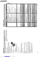
Page 16: ...red by lens cap When the LAMP indicator or the TEMP indicator is either on or blinking the main unit requires repairs The equipment connected to this projector is not turned on Hookup is not made correctly with other equipment The input source is not selected correctly The air inlet grill outlet grill or air filter is clogged with dust or some objects In this case the TEMP indicator does not light...

Page 17: ...HIDE MENU SOURCE COMPUTER AUTO POSITION EN 27 ENGLISH Specifications LCD projector LX D1010G AC100V 240V 50 60Hz 2 3 A 0 9 inch LCD panel 3 pieces for R G B Pixels 1 024 768 786 432 pixels Total 2 359 296 pixels Active pixel rate 99 99 or more each panel 16 770 000 colors F 1 7 2 0 f 33 2 mm 43 1 mm 150 W UHP 40 inch 300 inch aspect ratio 4 3 Resolution 640 x 400 1024 x 768 Compressed 1280 x 1024 ...

Page 18: ...i DIN 8P D SUB 9P for the connection PIN NO NAME I O 1 TXD IN 2 RTS IN 3 DTR IN 4 GND 5 CTS 5V IN OUT 6 DCD CLOCK OUT 7 RXD OUT 8 RI DATA OUT 1 2 6 8 5 3 1 Remote control 1 User manual 1 Quick reference card 2 Battery for remote 1 Carrying case Replacement part Option Not included in the box Spare Mercury lamp M 499DØØ7O3Ø SA What s included in the box 2 AC power cord 1 AV Audio Video cable 1 S Vi...

Page 19: ... by fax to Projection System Dept Also attach a copy to the projector From your office Manager Originator Date S N Detailed report of the symptoms Connected input signal Installation conditions environment Error display status with the self diagnosis function operating Total usage time of the light source lamp Detailed report of any repair attempts Previous malfunction history and repair history A...

Page 20: ...sts of parts and labor plus other sundry expenses JVC PSD REPAIR ORDER FORM OF LX D1010G 2 Be sure to keep the lens cap placed on any unit to be repaired Keep accessories in your custody until repaired units are returned to you 3 It is preferable that you pack the units to be repaired in the original caton box including cushion materials Then put the carton box into another larger carton box for f...

Page 21: ...these items carefully until the repairs have been completed It is necessary to prepare the shipping cases etc required for shipping projectors Always include a repair order sheet with all necessary items filled in Fill in all of the space with cushion such as bubble cushion REPAIR OREDR FORM LX D1010G CUSHION TOP M 803A557O10 PROJECTOR CUSHION BOTTOM M 803A558O10 PACKING CASE M 802B755O10 ...

Page 22: ... caution to avoid damaging or soiling these optical parts Use the cleaning paper etc and wipe out the soil At this time there is a fear of damaging the coated film Therefore avoid the use of solvents such as alcohol and the like 5 Use an air blower to remove dust from optical parts 6 Conductive paint is used on the insides of the top and bottom cases If the power is turned on while a board is in c...

Page 23: ...t one hour before starting work 1 Loosen the Screw A and remove the Lamp Cover 2 Loosen 2 Screws B 3 Remove the Lamp Ass y 4 2 Removing the Top Case Ass y 1 Remove 6 Screws C and slowly lift straight up the Top Case Ass y 2 Release the Connector ST lock by lightly pulling in the direction of the arrow and then disconnect the FPC wire Screw A Lamp Cover Handle Lamp Ass y Screws B Screws C Connector...

Page 24: ...PC wires of the LCD panels from the main board connector release the connector locks by lightly pulling upward When reassembling the Main PWB Ass y be sure to return the sheet to the top of the Main PWB Ass y If this sheet is forgotten there is danger of the Main PWB Ass y and others being damaged when the power is turned on 1 Remove the Top Case Ass y see 4 2 2 Remove the Lamp Power Unit see 4 3 ...

Page 25: ...Case Ass y see 4 2 2 Remove the Lamp Power Unit see 4 3 3 Remove the Main PWB Video PWB Inlet Switch PWB and Terminal Board Ass y see 4 4 4 Remove 2 Screws K 4 Screws L and connector SK connected the Video PWB Ass y and then remove the Main PWB Ass y 5 Remove 3 Screws M and 2 Screws N and then remove the Terminal Board 6 Remove 3 Screws O and then remove the Video PWB Ass y 7 Remove the Screw P th...

Page 26: ...PWB Inlet Switch PWB and Terminal Board Ass y see 4 4 4 Remove the Power Ass y see 4 6 5 Disconnect the Connector NP and then remove the Power Sub PWB Ass y 6 Remove the Screw R and then remove the Power Sub Holder 7 Remove the Power Holder R F and the Power Barrier 4 8 Removing the Intake Fan Front 1 Remove the Top Case Ass y see 4 2 2 Remove the Lamp Power Unit see 4 3 3 Remove the Main PWB Vide...

Page 27: ...ts such as prisms mirrors etc Use caution to avoid damaging or soiling these optical parts 1 Remove the Top Case Ass y see 4 2 2 Remove the Lamp Power Unit see 4 3 3 Remove the Main PWB Video PWB Inlet Switch PWB and Terminal Board Ass y see 4 4 4 Remove the Audio Ass y see 4 9 5 Remove 4 Screws W and the Metal Board X and then slowly lift up the Optical Ass y 4 11 Removing the Fan Small 1 Remove ...

Page 28: ...see 4 4 4 Remove the Optical Ass y see 4 10 5 Remove 6 Screws AA and then remove the Cooling Cover of the bottom 6 Hold the LCD Block to remove 3 Screws AB and then take out the LCD Block 4 14 Removing the Exhaust Fan Ass y 1 Remove the Top Case Ass y see 4 2 2 Remove the Lamp Power Unit see 4 3 3 Remove the Main PWB Video PWB Inlet Switch PWB and Terminal Board Ass y see 4 4 4 Remove the Optical ...

Page 29: ... of the markings The Polarizers are directional Position the Polarizer with the film side facing the LCD panel and with the marking upward on the side of the LCD panel FPC wire Polarizer Markings Glass Film LCD Panel For R red For G green For B blue 1 Remove the Top Case Ass y see 4 2 2 Remove the Lamp Power Unit see 4 3 3 Remove the Main PWB Video PWB Inlet Switch PWB and Terminal Board Ass y see...

Page 30: ...ents will be very difficult 2 Adjust to balance the light on the screen and the G LCD Panel surfaces evenly by moving the part A in the direction of the arrow Fix the part A at the best position 3 Adjust to balance the light on the screen and the R LCD Panel surfaces evenly by moving the part A in the direction of the arrow Fix the part A at the best position 4 Adjust to balance the light on the s...

Page 31: ... Ass y Inlet Switch PWB Ass y and Terminal Board 4 Connect all cables to the Lamp on Tool 5 Connect the AC Power Cord and then turn on the Power Switch 6 Turn on the switches in the order of POWER ON FAN ON and LAMP ON 7 The lamp turn on and then adjust or check 8 After finishing the work turn off the switch of LAMP ON 9 Wait for 2 minutes after lamp off and then turn off the switches in the order...

Page 32: ...LX D1010G 4 10 PA012 Memo ...

Page 33: ...tart Windows 95 Double click on the Accessories folder Double click on the Hyper Terminal folder Double click on the Hypertrm icon to open the Hyper Terminal window When the New Connection dialogue box opens input an appropriate name and select an icon then click the OK button When the Phone Number dialogue box opens set the connection using the port where the RS 232C cable is connected and then c...

Page 34: ...ASCII then click on the OK button Item Setting ASCII Sending Send line ends with line feeds Echo typed characters locally Line delay 1000ms Character delay 10ms ASCII Receiving Append line feeds to incoming line ends 3 Exiting Click on the Close button in the upper right corner of the Hyper Terminal window to close Hyper Terminal Setting emulation Click on the Close button ...

Page 35: ...RS 232C cable provided with the projector 2 Connection Method Before using the RS 232C cable to connect make sure the power of the projector and personal computer are turned off Use the RS 232C cable provided with the projector to connect the projector RS 232C terminal and the COM port of the personal computer Startup Turn on the power of the projector and the personal computer in that order Exiti...

Page 36: ...LX D1010G 6 2 PA012 Memo ...

Page 37: ...en using an XGA signal generator This software can be downloaded from JS Net 1 on the Internet 1 http gisa yh jvc victor co jp 2 Connection Method XGA signal generator or personal computer RS 232C cable Personal computer Projector RGB IN RS 232C 3 Test signals XGA signal H 48 36 kHz V 60 00 Hz The timing and pattern are shown below XGA signal vertical frequency 60Hz timing DOT CLOCK MHz 65 0 HP DO...

Page 38: ...ary 1 A D converter input amplitude Perform when the Main PWB Ass y has been replaced 2 Ghost Perform when the Ghosts are prominent in the video after either the Main PWB Ass y or the LCD Block has been replaced 3 Flicker Perform when the Flicker is prominent in the video after either the Main PWB Ass y or the LCD Block has been replaced 4 Gray color balance Perform when the Color Balance is lost ...

Page 39: ...command 00 30C in the Hyper Terminal window to minimize ghosts in the red image In the input the value from among the 5 types of 008 009 00A 00B and 00C so that the ghost can be reduced to a minimize value resulting in the entirely well balanced screen center and periphery of four corners 3 4 Input the write command 00 1829 in the Hyper Terminal window to write the changed value to the EEPROM In t...

Page 40: ...rts stock 4 5 Input the write command 00 1810 in the Hyper Terminal window to write the changed value to the EEPROM Enter the value input in the in item 4 4 Green 6 Input the XGA signal Green 50 alternate line horizontal pattern No 23 7 Input the adjustment command 00 222 in the Hyper Terminal window to minimize flicker in the green image Input the hexadecimal digit from 00 to FF in the to minimiz...

Page 41: ...t 50 to be within the adjustment specification only for the y value If the adjustment value is increased the y value will be increased also If the adjustment value is decreased the y value will be decreased also Input the adjustment command 00 802 in the Hyper Terminal window In the input the numeral of the decimal notation from 20 to 05 to be within the adjustment specification for the y value It...

Page 42: ...t 20 to be within the adjustment specification only for the y value If the adjustment value is increased the y value will be increased also If the adjustment value is decreased the y value will be decreased also Input the adjustment command 00 822 in the Hyper Terminal window In the input the numeral of the decimal notation from 20 to 05 to be within the adjustment specification for the y value It...

Page 43: ...VICE MENU2 L ON COUNT 99 Number of times the lamp was turned on This count the turn on action whether succeeded or failed L NG COUNT 2 Number of times the lamp on was failed excluding the lamp went out TEMP ERR TIME 0H 0M The SET TIME when the power turned off caused by unusual temperature If the above power off has been nothing 0H 0M is displayed IN TEMP 30 0 ゚ C 0 0 Temperature of the intake air...

Page 44: ...ME FINE ON OFF Always FINE Mode This function is unstable 35 KEY STONE 35 OFF 35 Setting for 35 Select OFF to perform the keystone adjustment 8 3 Tips to initialize menu contents and warning record Turn on the main power switch Press MENU ENTER and button of the Operation Unit simultaneously to initialize Caution The initialized menu will turn to a display in English If you find it necessary to se...

Page 45: ... L in the Hyper Terminal window The lamp time will be returned in the Hyper Terminal window as the return command Record the part below on paper etc Example 00 l000217 2 hours 17 minutes Example 00 l500000 500 hours Tern off the main power switch and replace the Main PWB Ass y Perform the operations in and then open the Hyper Terminal window Input the value recorded in in the Hyper Terminal window...

Page 46: ...B 50 2 00 1908 00 1908 D D 00 FF R 20 1 00 1903 00 1903 D D 00 FF R 20 2 00 1909 00 1909 D D 00 FF G 20 1 00 1904 00 1904 D D 00 FF G 20 2 00 190A 00 190A D D 00 FF B 20 1 00 1905 00 1905 D D 00 FF Color Temperature 20 B 20 2 00 190B 00 190B D D 00 FF Service Command Table Contents Read Commands Write Commands Data Range Remarks SET TIME 00 s 00 sHHHHHMM Reply 00 sHHHHHMM HHHHH hours MM minutes LA...

Page 47: ...tall pcgc7e xga ini file in the Windows folder 2 Program startup Before using the RS 232C cable to connect make sure the power supplies of the projector and personal computer are turned off Use the RS 232C cable provided with the projector to connect the projector RS 232C terminal and the COM port of the personal computer Turn on the main power switch of the projector Turn on the power of the pers...

Page 48: ...ed correctly the data will not be displayed in the main dialogue box 5 Clearing the warning history After correcting the error perform the clearing the warning history When the ALL CLEAR button in the main dialogue box is clicked a command will be sent from the personal computer to the projector to clear the all of warning history and the error display will be cleared 6 When a communication error ...

Page 49: ...set the lamp time to recover written as Manual in the Reset 3 Emergency power on Emergency power on is possible when the power cannot be turned on using the normal method due to a standby power short or switched power short and it is necessary to turn the power on to detect errors Turning the power on The power can be turned on during a sensor check by pressing the HIDE ENTER and VIDEO buttons of ...

Page 50: ... prohibited for safety Power Sub SN Connector Lamp cover Auto 5 Red Green alternately Off Off No power on Filter cover open for dust in prevention Power Sub SN Connector Filter cover side Auto 6 Red Green alternately Off Red flash No power on Missing thermistor Main SZ Connector Auto Red Green alternately Green Red flash 2 No power on IIC bus 2 failure DECODER Main IC2A2 ICLK1 45p IDA1 Auto 7 Red ...

Page 51: ...stem External checkout Checks for external problems case damage etc See page 12 2 Internal cable connection checkout Checks the cable connector connections See page 12 3 No standby status The power indicator does not light See page 12 4 When the self diagnosis function shows a standby power short See page 12 5 When the self diagnosis function shows a switched power short See page 12 6 When the lam...

Page 52: ...othly Is the lens dirty or damaged Is the Filter Cover installed correctly to the Bottom Case Unit Has the protuberance A of the Filter Cover frame been damaged Is the Filter dirty Is the Blower intake dirty Are there any traces of deformation or burning discoloration in the plastic frame Is the lamp damaged Is the Lamp connector discolored Is the Lamp Cover installed correctly to the Bottom Case ...

Page 53: ... installation Main PWB Ass y CN ST Main PWB Ass y CN SZ Main PWB Ass y CN SV Audio PWB Ass y CN GV Main PWB Ass y CN SL Preamp PWB Ass y CN AL Main PWB Ass y CN SRX CN SGX CN SBX Video PWB Ass y Main PWB Ass y CN SK Video PWB Ass y CN TK Main PWB Ass y CN SF Power Sub PWB Ass y CN NF Power PWB Ass y CN RB Power Sub PWB Ass y CN NB Audio PWB Ass y CN GN Power Sub PWB Ass y CN NN Main PWB Ass y CN S...

Page 54: ...Ass y failure Yes The thermostat is on the Lamp Ass y Is there 5V or more at pin 6 of the CN NF Yes Disconnect the SF connector from the Main PWB Ass y No If you replace the Main PWB Ass y is the status become standby Check the circuit around the IC950 IC951 and replace the parts if necessary specially Z954 Z955 No The Operation Unit failure No Yes LED does not light Check the STBY5 IC950 primary ...

Page 55: ...pin 8 of the RD connector Yes No Connect or replace the lead Is there 17V or more between both lead of the C952 Check the circuit around the IC907 Disconnect the SD connector from the Main PWB Ass y No Yes The Main PWB Ass y failure No Yes Check the STBY5 Z950 or Z951 failure Check the circuit around the IC904 or IC907 ...

Page 56: ...C3A1 etc No Yes Is there 12V or more at the CN RD pin 4 Yes IC905 is failed or the around circuit short No Yes When the SW5D failure Is there 2V or more at the CN RB pin 2 No Q952 or Q953 is failed or the around circuit short Yes When the SW3 3 failure When the SW15 5 failure When the SW12 failure When the SW5A failure Is there 5V or more at the CN RD pin 6 Q907 is failed or the around circuit of ...

Page 57: ...nnectors Yes Is there 20V between both leads of the Z900 Check the around circuit of the IC902 and PC901 The Lamp Power Unit failure Remove the Main PWB Ass y and then connect the Lamp on Tool Turn on the POWER ON FAN ON and LAMP ON switches Disconnect the RE lead and then turn on the FAN ON switch The Main PWB Ass y failure No Yes No PFC circuit failure Check the around circuit of the IC901 and Q...

Page 58: ...SGX and SBX connectors Check the video signal line around IC800 804 IC8A0 8A4 and IC8M0 8M4D Check the panel control line around IC5A0 5A4 If the waveforms are normally the LCD Panel is failed If input signal is displayed normally and Menu display is abnormal check the around of the SGRAM IC4S0 No Yes Is the input video signal displayed normally The input analog circuit for the computer terminal i...

Page 59: ...fter servicing route all wires in their original position Workers shall put on the wristband to protect LCD Panel against static electricity during the operations Clamping zone Hidden clamping zone Lead dress in the Bottom Case Unit Cushion Lead wire Cushion Power Earth Cushion Cushion The lead wire should be fixed firmly by the cushion Power Earth There should be no slack in the lead wire when th...

Page 60: ...toward the left to take in slack in the wires Put the wire into the gap to take in slack Put the wire into the gap to take in slack Cushion SF SD SZ SW SN SBX SGX SRX SY SV ST SX SL The NN GN lead wire should cross the SA CB2 lead wire Cushion Cushion Yellow Green lead Run this earth wire above the SY and SV lead wires The wire put into the gap should not interfere the lighting part and the screw ...

Page 61: ...POWER OFF L POWER ON H 5V L 0V 11 FAN ON OUT FAN ON signal H FAN ON L FAN OFF H 5V L 0V 12 13 E To Power Sub PWB Ass y Connector SA CB2 Signal Name IN OUT Function Summary Remark 1 FGND GND for fans 2 FANV IN Power for FAN 7 13V 3 P FANC OUT POWER FAN CONTROL 0 4V 4 O FANC OUT OPTICAL FAN CONTROL 0 4V 5 DGND GND for digital circuit 6 STBY5 IN Standby Power 5V DC 5V 7 DGND GND for digital circuit 8...

Page 62: ...9V 3 VOL OUT Audio control 0 5V 4 S MUTE Audio muting signal muting L 0V 5V 5 AULRM Audio output 1Vp p 6 GND AU GND for audio circuit 7 DGND GND for digital circuit 8 RSI0 IN Remote control serial signal rear L sending data H 5V L 0V 9 STBY5 OUT Standby Power 5V DC 5V E To Preamp PWB Ass y Connector SA CB2 Signal Name IN OUT Function Summary Remark 1 DGND 2 RSI1 IN Remote control serial signal fro...

Page 63: ... LED Green control signal LED on L H 3 3V L 0V 8 LEDPRZ OUT POWER LED Red control signal LED on L H 3 3V L 0V 9 LEDTRZ OUT TEMP LED Red control signal LED on L H 3 3V L 0V 10 LEDLGZ OUT LAMP LED Green control signal LED on L H 3 3V L 0V 11 LEDLRZ OUT LAMP LED Red control signal LED on L H 3 3V L 0V 12 LEDTGZ OUT TEMP LED Green control signal LED on L H 3 3V L 0V E To Thermistor Ass y Connector SA ...

Page 64: ...se signal of RCLY 0 15 5V reverse every 1H 56 8kHz 30 RDY OUT Start pulse of Y shift resistor 0 15 5V 1V 72 5Hz E To LCD Panel G Connector SA CB2 Signal Name IN OUT Function Summary Remark 1 GDY OUT Start pulse of N shift resistor 0 15 5V 1V 72 5Hz 2 GCLYZ OUT Transmit clock of Y shift resistor reverse signal of GCLY 0 15 5V reverse every 1H 56 8kHz 3 GCLY OUT Transmit clock of Y shift resistor 0 ...

Page 65: ...ID4 OUT B video signal 2 12V reverse every 1H 56 8kHz 15 BVID3 OUT B video signal 2 12V reverse every 1H 56 8kHz 16 BVID2 OUT B video signal 2 12V reverse every 1H 56 8kHz 17 BVID1 OUT B video signal 2 12V reverse every 1H 56 8kHz 18 AGND Negative power for X driver GND GND 19 BDIRX OUT X driver drive direction reverse signal front L rear H L 0V H 15 5V 20 BENBX1 OUT X driver enable pulse 0 15 5V ...

Page 66: ...N OUT FAN ON signal H FAN ON L FAN OFF H 5V L 0V 4 FGND GND for FAN 5 14V OUT Secondary output voltage 14V DC 14V 6 DGND GND for digital circuit 7 STBY5 OUT Standby 5V DC 5V 3 Power Sub PWB Ass y E To Intake Fan front Connector SA CB2 Signal Name IN OUT Function Summary Remark 1 FGND GND for FAN 2 FANP OUT Power for Intake Fan front 7 13V 3 P FSTOP IN Fan lock sensor for Intake Fan front L normal ...

Page 67: ... PA012 15 1 LX D1010G 15 BLOCK DIAGRAMS ...

Page 68: ... PA012 15 2 LX D1010G ...

Page 69: ...LX D1010G PA012 15 3 ...

Page 70: ...LX D1010G PA012 16 1 ...

Page 71: ...O20 AC POWER CORD for Europe 13 M 246C381O10 AV Audio Video CABLE 4 M 246C367O10 PS 2 ADAPTOR 14 M 939P795O20 REMOTE CONTROLLER 5 M 246C382O10 PC RGB CABLE 15 BATTERY for remote x 2 6 M 246C366O10 RS 232C CABLE 16 M 772P032O10 CARRYING CASE 7 M 803A558O10 CUSHION BOTTOM 17 M 246C376O10 USB CABLE 8 M 803A557O10 CUSHION TOP 18 M 246C384O10 S VIDEO CABLE 9 M 871D294O10 INST BOOK LX D1010G 19 M 411D02...

Page 72: ...LX D1010G Parts 2 PA012 Final Assembly M 1 1 3 2 6 4 5 2 6 7 1 8 9 1 10 11 2 12 1 13 14 2 15 16 17 4 18 19 6 20 22 21 1 23 24 2 25 26 1 27 28 29 ...

Page 73: ...ERMINAL BORD ASS Y 11 M 669D329O10 SCREW 2 12 M 669D561O20 SCREW 1 13 M 939P794O10 LAMP POWER UNIT 14 M 669D564O30 SCREW 2 15 METAL BOARD B 16 OPTICAL ASS Y 17 M 669D564O40 SCREW 4 18 POWER ASS Y 19 M 669D564O30 SCREW 6 20 M 752C251O30 LAMP COVER 21 M 669D425O20 SCREW 1 22 M 761B364O10 LENS CAP 23 M 589B013O10 ADJUSTER 24 M 669D368O40 SCREW 2 25 AUDIO ASS Y 26 M 669D564O30 SCREW 1 27 M 640D990O10 ...

Page 74: ...30 SCREW 2 4 M 669D552O10 SCREW 4 5 M 761B363O40 TERMINAL BOARD 6 M 669D199O30 SCREW 3 7 M 669D566O10 SCREW 2 8 M 935C922O09 INLET SWITCH PWB ASS Y 9 M 669D245O10 SCREW 1 10 M 935C920O01 VIDEO PWB ASS Y 11 M 669D212O20 SCREW 3 12 PIN SHIELD 13 M 433C026O40 POWER SWITCH 14 M 283D107O30 FUSE F9F1 M 452C247O20 FPC CONNECTOR R B 2 SRX and SBX refer to page 13 2 M 452C233O20 FPC CONNECTOR G SGX refer t...

Page 75: ...PART No PART NAME DESCRIPTION 1 SUB POWER HOLDER 6 M 935C921O01 POWER SUB PWB ASS Y 2 M 669D329O10 SCREW 1 7 M 621C827O10 POWER HOLDER F 3 POWER BARRIER 8 M 288P160O50 FAN 4 M 621C828O10 POWER HOLDER R 9 M 669D220O70 SCREW 2 5 M 935B260O01 POWER PWB ASS Y 10 M 299P194O20 THERMOSTAT Z900 1 2 1 3 4 5 6 7 8 9 2 10 ...

Page 76: ...Parts 6 PA012 Audio Ass y M 4 Parts List Audio Ass y M 4 REF No PART No PART NAME DESCRIPTION 1 M 480P052O10 SPEAKER 2 M 650P200O60 SCREW 2 3 AUDIO HOLDER 4 M 935C923O01 AUDIO PWB ASS Y 5 M 669D329O10 SCREW 1 1 2 ...

Page 77: ...LX D1010G PA012 Parts 7 Memo ...

Page 78: ...LX D1010G Parts 8 PA012 Optical Ass y M 5 1 2 2 3 4 2 4 2 4 2 5 8 6 7 2 8 9 3 10 11 2 12 13 13 13 14 15 6 16 17 2 18 19 4 20 21 1 22 23 2 ...

Page 79: ... 669D220O10 SCREW 2 8 M 499D007O10 LCD BLOCK 9 M 669D329O10 SCREW 3 10 M 499D007O50 BLOWER Intake 11 Attached to No 10 SCREW 2 12 BLOWER HOLDER 13 M 669D329O10 SCREW 3 14 COOLING COVER 15 M 669D317O10 SCREW 6 16 M 499D007O30 SA LAMP ASS Y 17 Attached to No 16 SCREW 2 18 M 499D007O20 LENS UNIT 19 M 669D329O20 SCREW 4 20 M 499D007O90 THERMISTOR ASS Y 21 M 669D220O10 SCREW 1 22 M 499D007O60 FAN ASS Y...

Page 80: ...6 Install Direction Light source side Lamp side PBS Plane Uneven POLARIZER R G B Plane Film side Projection lens side Parts List Inside of the Optical Ass y M 6 REF No PART No PART NAME DESCRIPTION 1 M 499D007O80 PBS ASS Y 2 M 499D007O40 POLARIZER R G B 1 2 ...

Page 81: ...しろページ ...

Page 82: ...LX D1010G Printed in Japan VP 0002 K K VICTOR COMPANY OF JAPAN LIMITED Projection System Department 1644 Shimotsuruma Yamato Kanagawa 242 8514 Japan ...

Reviews: