background image

5

ENGLISH

INSTALLATION

5. How To Connect Cables To The DVD-ROM Drive

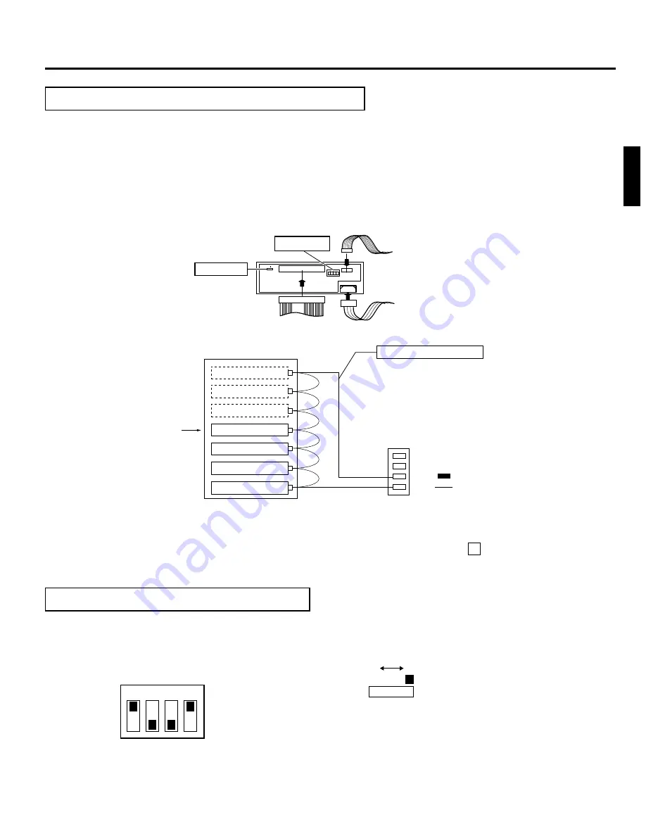
1. Connect the power supply cable, control cable and SCSI cable to the connectors at the rear of the DVD-ROM Drive.

Connect to the drive the power supply cable and control cable which extend from the side of the DVD-ROM drive
installation slot.

With the MC-2100U and the MC-8100U models be sure to connect a control cable with the same component No., as
the drive bay No., otherwise proper operation may not be possible.

Insert  all connectors firmly.

6. How To Set The Dip and Slide Switches

 Always turn OFF the power of Library when you set the dip switch modes.

1. TERM : This selects the use of the built-in terminator.

To use the built-in drive terminator, set the TERM of the drive to ON and the TERM of other drives to OFF.

When not using the built-in terminator, attach an active SCSI terminator to the OUT side of the SCSI connector.
In this case, set the TERM of all built-in drives to OFF.

Power supply cable

Control cable

SCSI cable

Slide switch

14p

4p

Dip switches

W

N

Rear section of the DVD-ROM Drive

 SCSI cables should be connected as a daisy chain connection. Each connector may be connected to the drive

positions as illustrated in the diagram.

 Terminate the physical end of the SCSI bus. To use the built-in drive terminator, read 6 -1.

 It is recommended to use an external terminator to improve the stability of the SCSI bus communications.

Connection example of a SCSI cable

(Factory setting)

ON

OFF

1

TERM

ID 2

ID 1

ID 0

2

3

4

W

N

DIP switch

Slide switch

DVD-ROM Drive

DVD-ROM Drive

Library SCSI board

SCSI connector

To be connected with host 
computer's SCSI host adapter

Connect an active terminator.

OUT 2

IN     2

OUT 1

IN     1

Internal SCSI ribbon cable

• Up to six drives can be connected normally.

(But only four drives in the case of the MC-2100U 
and the MC-8100U)

DVD-ROM Drive

(Terminate here)

Summary of Contents for MC-D207U

Page 1: ...ONS DVD ROM DRIVE For Customer Use Enter below the Model No and Serial No which are located at the top of the unit Retain this information for future reference Model No MC D207U Serial No This instruction manual has been manufactured from 100 recycled paper ...

Page 2: ...nstructions carefully in order to obtain the best possible performance 1 DANGER Invisivle laser radiation will occur when the unit is open with a failed or defeated interlock 2 CAUTION Do not open the top cover There are no user serviceable parts inside the unit leave all servicing to quali fied service personnel ...

Page 3: ...the section HOWTO OPENTHE DOOR DURING OPERATION in the in structions for the JVC CD ROM or CD DVD Library 1 Select the DOOR OPEN MODE on the MENU screen of the LCD display section 2 Press and hold the SELECT switch for five seconds 3 Turn off the power of the JVC Library when the YOU MAY OPEN THE DOOR or THE DOOR CAN BE OPENED message is displayed on the LCD display section 4 Insert the key in the...

Page 4: ...cover 4 How to Install the DVD ROM Drive 1 Install drive from the No 1 to No 6 slot in that order without skipping 䡵Starting installation from the lowest No 1 slot will simplify future installation work 1 Insert the drive from the rear of the JVC CD ROM or CD DVD Library 䡵 Pay attention not to damage the sensor slit 䡵 Always insert the DVD ROM Drive correctly 䡵 Check that cables connected on the r...

Page 5: ...attach an active SCSI terminator to the OUT side of the SCSI connector In this case set the TERM of all built in drives to OFF Power supply cable Control cable SCSI cable Slide switch 14p 4p Dip switches W N Rear section of the DVD ROM Drive 䡵 SCSI cables should be connected as a daisy chain connection Each connector may be connected to the drive positions as illustrated in the diagram 䡵 Terminate...

Page 6: ...re to set the slide switch to N for use The position W is provided for service use only 7 How To Refit The Drive Storage Cover 䡵 Always refit the drive storage cover before switching ON the JVC CD ROM or CD DVD Library 1 Fasten the cover with the screws that were removed in the procedure 2 1 Default factory setting SCSI ID No Switch Remarks ID2 OFF OFF OFF OFF ON ON ON ON ID1 OFF OFF ON ON OFF OFF...

Page 7: ...gle layer Approx 10 Mbytes s max 7X max CAV DVD ROM Double Layer Approx 10 Mbytes s max 7X max CAV DVD R 3 95 GB or 4 7 GB Appr ox 3 46 Mbytes s max 2 3X max CAV DVD RAM Single sided 4 7 GB single sided 2 6 GB Approx 2 77 Mbytes s typ 2X max CAV Burst 05 Mbytes s asynchronous 10 Mbytes s synchronous Average access time DVD ROM 135 ms 1 3 stroke typ CD ROM 125 ms The above values were measured usin...

Page 8: ...COMPANY OF JAPAN LIMITED Printed in Japan LST0038 001B 2002 VICTOR COMPANY OF JAPAN LIMITED is a registered Trademark owned by VICTOR COMPANY OF JAPAN LTD is a registered Trademark in JAPAN the U S A the U K and many other countries ...

Reviews: