MX-G70
1-10
Prior to performing the following procedure, remove
the metal cover, the CD changer mechanism
assembly and the rear panel.
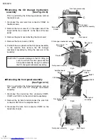
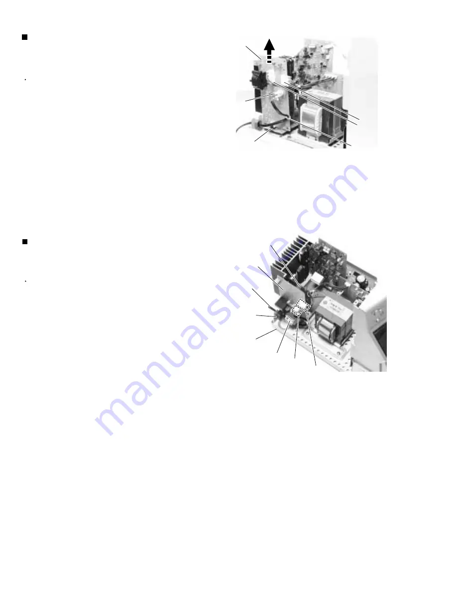
Disconnect the wires from connector CN218, CN219
and CN250 on the power supply board respectively.
Remove the tie band attaching the wire to the power
supply board.
Move the power cord stopper upward and pull out it
from the base chassis.
Disconnect connector CN213 on the power supply
board from the regulator board.
1.
2.
3.
4.
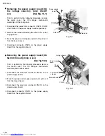
Removing the power supply board (On
the voltage selector). (only US,UW
ver.) (See Fig. 19-1)
Removing the power supply board (On
the ECO Circuit). (Only A ver.)
(See Fig.19-2)
Prior to performing the following procedure, remove
the metal cover, the CD changer mechanism
assembly and the rear panel.
Disconnect the wire from connector CN250 on the
power supply board.
Move the power cord stopper upward and pull out it
from the base chassis.
Disconnect the wire from connector CN218 on the
power supply board.
Disconnect connector CN213 on the power supply
board from the regulator board.
1.
2.
3.
4.
Fig.19-1
Power supply
board
Tie band
CN218
CN219
CN213
CN250
Fig.19-2
Voltage board
CN218
Power supply
board
CN250
Power cord
stopper
Base chassis
Power
cord
CN213


