MX-G70
1-31
1
2
3
4
5
6
7
8
9
10
11
12
13
14
15
16
17
18
19
20
21
22
23
24
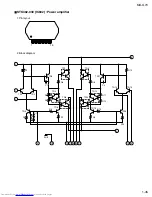
AMP
Pre
Source
CTRL
AMP
ALC
ALC
AMP
AMP
EQ
CTRL
ALC
REPPLE
REJ
Pre
Pre
L1
L2
R1
R2
NF2
NF1
OUT1
OUT2
EQ1
EQ2
CTL2
CTL1
RIN2
RIN1
RNF2
RNF1
ROUT2
ROUT1
LC
LPF
GND
EQ
CTL
RF
VCC
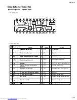
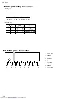
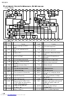
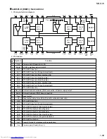
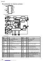
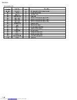
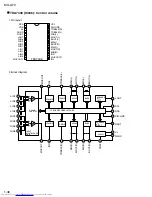
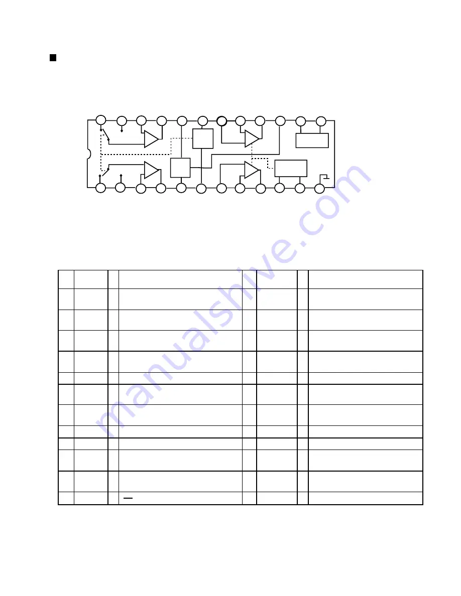
AN7345(IC302) : PB/REC AMP
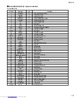
2. Pin Function
Pin
No.
Symbol
I/O
Function
Function
I/O
Symbol
Pin
No.
1
2
3
4
5
6
7
8
9
10
11
12
13
14
15
I
I
16
17
18
19
20
21
22
23
24
I
I
O
I
I
Playback amplifier output
I
I
I
RIN1
OUT1
1. Block diagram
Playback amplifier input
R1
R2
I
Playback amplifier input
NF2
Playback amplifier negative feedback
OUT2
Playback amplifier output
EQ2
I
Equalizer
CTL2
I
Pre Amplifier input switching time
constant
RIN2
I
Recording amplifier input
RNF2
I
Recording amplifier negative feedback
ROUT2
O
Recording amplifier output
O
LC
I
ALC low cut
LPF
I
ALC low pass filter
GND
I
Vcc
Power supply
RF
I
Ripple filter
EQCTL
EQ control
ROUT1
O
Recording amplifier output
RNF1
Recording amplifier negative feedback
I
Recording amplifier input
CTL1
Pre amplifier input switching control
EQ1
Equalizer
Playback amplifier negative feedback
NF1
L2
I
L1
Playback amplifier input
Playback amplifier input
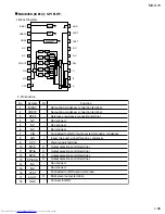
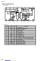
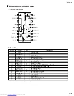
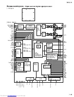
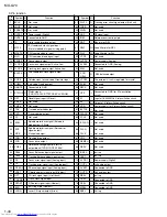
Description of major ICs

