1-20
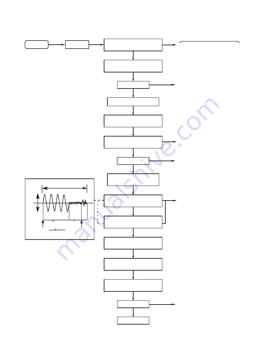
Check Point
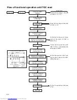
Confirm that the voltage at the pin5
of CN602 is "H"\"L"\"H".
Flow of functional operation until TOC read
Check that the voltage at the pin40
of IC601 is + 5V?
Confirm that the Focus error S-cuve
signal at the pin32 of IC601 is
approx.2Vp-p
Confirm that the signal from pin24
IC601 is 0V as a accelerated pulse
during approx.400ms.
Confirm the waveform of the Track-
ing error signal. at the pin 20 of IC611
(R643) (See fig-1)
Confirm the eys-pattern at the lead
of Tp3
Slider turns REST
SW ON.
Automatic tuning
of TE offset
Laser ON
Detection of disc
Automatic tuning of
Focus offset
Automatic measurement of
Focus S-curve amplitude
Power ON Play Key
Disc is rotated
Focus servo ON
(Tracking servo ON)
Automatic measurement of
Tracking error amplitude
Automatic tuning of
Tracking error balance
Automatic tuning of
Focus error balance
Automatic tuning of
Focus error gain
Automatic tuning of
Tracking error gain
TOC reading
Play a disc
Tracking error waveform at TOC reading
Approx
1.8V
VREF
pin 20 of
IC611(TE)
Approx.3sec
Disc states
to rotate
Tracking
servo
off states
Tracking
servo
on states
Disc to be
braked to
stop
TOC reading
finishes
Automatic measurement
of TE amplitude and
automatic tuning of
TE balance
500mv/div
2ms/div Fig.1
Summary of Contents for MX-K10/30
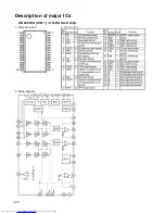
Page 23: ...1 23 BA5936S IC621 6 channel BTL driver 1 Block diagram 2 Pin function ...
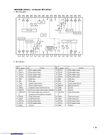
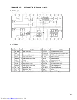
Page 25: ...1 25 LA1823DIP IC1 1chip AM FM MPX tuner system 1 Block diagram 2 Pin function ...
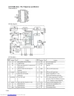
Page 26: ...1 26 LC72136N IC2 PLL Frequency synthesizer 1 Terminal layout 2 Block diagram 3 Pin function ...
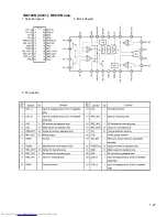
Page 27: ...1 27 TA8189N IC401 REC PB amp 1 Terminal layout 2 Block diagram 3 Pin function ...
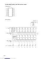
Page 28: ...1 28 TC74HC4094AP IC402 8 bit shift and store resister 1 Terminal layout 2 Block diagram ...
Page 29: ...1 29 TDA7440D IC101 Audio processor 1 Terminal layout 2 Block diagram ...


