
PD-42DXT
1-50 (No.52108)
Item
Mesuring
instrument
Test point
Adjustment part
Description
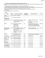
SUB-SCREEN
A-D
CONVERTER
GAIN
Remote control
unit
Signal generator
[8. PP]
ADM012: (NO DISPLAY)
(G GAIN)
[1.PICTURE/SOUND]
S13: RDRV
(R DRIVE)
S15: GDRV
(G DRIVE)
S17: BDRV
(B DRIVE)
S19: CUTR
(R CUTOFF)
S21: CUTG
(G CUTOFF)
S23: CUTB
(B CUTOFF)
F44: (NO DISPLAY)
(PICTURE CONTROL)
F45: (NO DISPLAY)
(SWITCH TO PICTURE
CONTROL MODE)
F46: OUT LV.
(Output Level Upon
Detection)
F47: LMT BTM
(Minimum Value
Upon Detection)
F48: LMT TOP
(Maximum Value
Upon Detection)
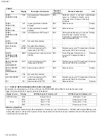
(1) Set "
映像選択
" to
スタンダード
.
(2) Set "
画面サイズ
" to
フルモード
.
(3) Select "
映像調節
" and set white balance to "
低い色
温度
".
(4) Set Dual Screen mode.
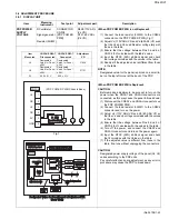
(5) Input NTSC 100% white signal to both right and left
screen.
(6) Select "1. PICTURE/SOUND" from the Service
Menu for the right screen.
(7) Set <S13> (R DRIVE), <S15> (G DRIVE) and
<S17> (B DRIVE) to "255".
(8) Set <S19> (R CUTOFF), <S21> (G CUTOFF) and
<S23> (B CUTOFF) to "125".
(9) Set <F44> (PICTURE CONTROL) to "001" and
<F45> (SWITCH TO PICTURE CONTROL MODE)
to "000" to set Y ADJUST MAX mode.
(10) Set <F46>(Output Level Upon Detection), <F47>
(Minimum Value Upon Detection) and <F48>
(Maximum Value Upon Detection) to values as
shown in the left table.
(11) Press the [
消音
] key to save the values upon
adjustment.
(12) Select "8. PP" from the Service Menu.
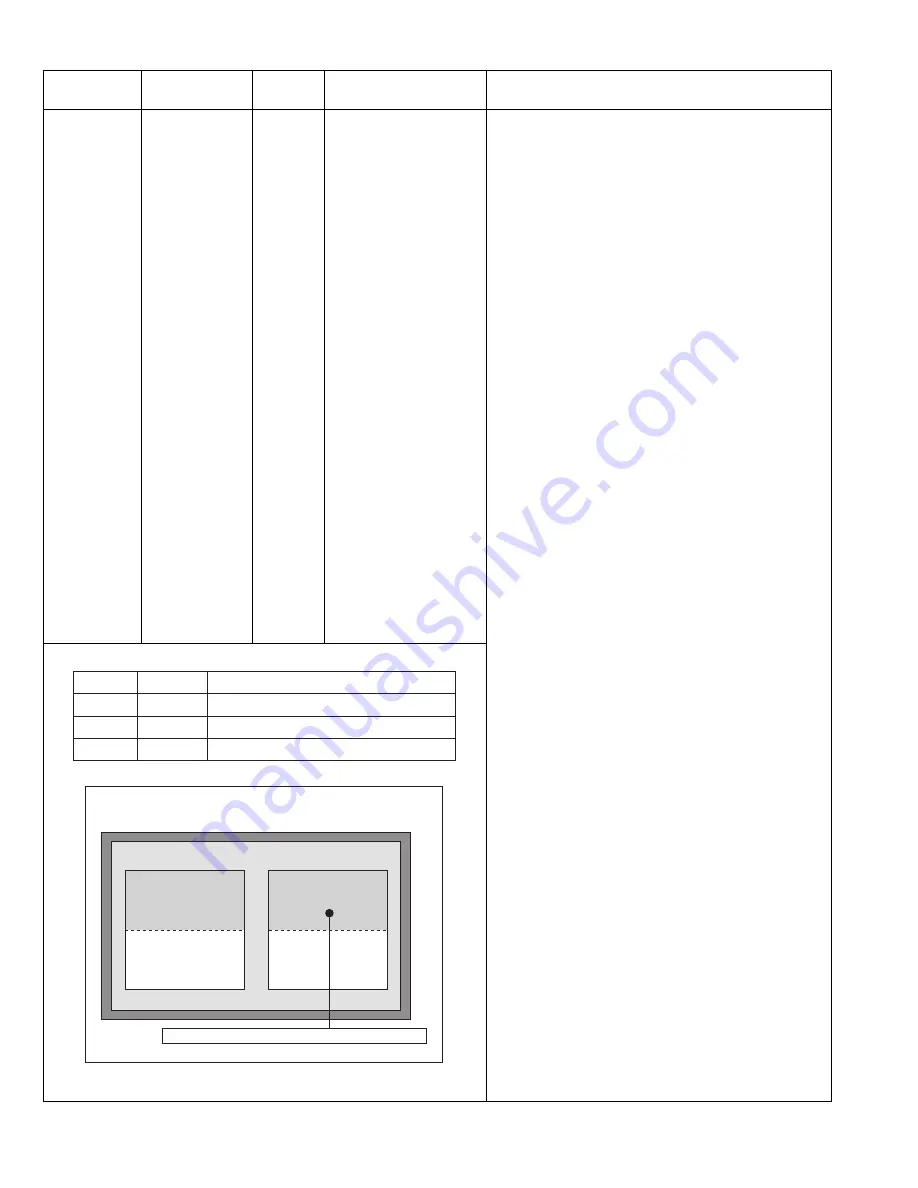
(13) Adjust <ADM010> (G OFFSET) so that upper right
part of the screen is the brightest. (Diagram 8)
(14) Press the [
消音
] key to save the values upon
adjustment.
(15) Check the black level adjusted in BLACK LEVEL
adjustment. Adjust the black level again if it is not
proper.
(16) Select "1. PICTURE/SOUND" from the Service
Menu.
(17) Set <F44> (PICTURE CONTROL) to "000" to set Y
ADJUST MAX MODE.
(18) Press the [
消音
] key to save the values upon
adjustment.
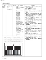
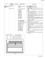
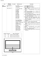
Fig.8
Item No. Preset value
Item to be adjusted
F46
090
Output Level Upon Detection
F47
168
Minimum Value Upon Detection
F48
168
Maximum Value Upon Detection
Dual Screen Mode
Adjust the upper half of the right screen to the brightest.
Summary of Contents for pd-42dxt
Page 55: ...PD 42DXT No 52108 1 55 ...


