background image

SERVICE MANUAL

COPYRIGHT © 2005 Victor Company of Japan, Limited

No.YA229

2005/2

PDP COLOUR TELEVISION

YA229

2005

2

PD-Z50DX4,

PD-Z50DX4

/S

TABLE OF CONTENTS

1

PRECAUTION. . . . . . . . . . . . . . . . . . . . . . . . . . . . . . . . . . . . . . . . . . . . . . . . . . . . . . . . . . . . . . . . . . . . . . . . .  1-3

2

SPECIFIC SERVICE INSTRUCTIONS . . . . . . . . . . . . . . . . . . . . . . . . . . . . . . . . . . . . . . . . . . . . . . . . . . . . . .  1-6

3

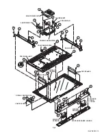
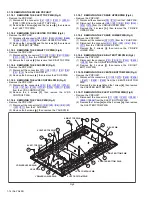
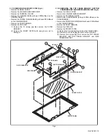
DISASSEMBLY  . . . . . . . . . . . . . . . . . . . . . . . . . . . . . . . . . . . . . . . . . . . . . . . . . . . . . . . . . . . . . . . . . . . . . .  1-10

4

ADJUSTMENT . . . . . . . . . . . . . . . . . . . . . . . . . . . . . . . . . . . . . . . . . . . . . . . . . . . . . . . . . . . . . . . . . . . . . . .  1-21

5

TROUBLESHOOTING . . . . . . . . . . . . . . . . . . . . . . . . . . . . . . . . . . . . . . . . . . . . . . . . . . . . . . . . . . . . . . . . .  1-29

BASIC CHASSIS

FP2

TU-Z50DX4, TU-Z50DX4/S

[RECEIVER UNIT]

VM-Z50DX4, VM-Z50DX4/S

[PLASMA DISPLAY UNIT]

POWER

Summary of Contents for PD-Z50DX4

Page 1: ...OLOUR TELEVISION YA229 2005 2 PD Z50DX4 PD Z50DX4 S TABLE OF CONTENTS 1 PRECAUTION 1 3 2 SPECIFIC SERVICE INSTRUCTIONS 1 6 3 DISASSEMBLY 1 10 4 ADJUSTMENT 1 21 5 TROUBLESHOOTING 1 29 BASIC CHASSIS FP2 TU Z50DX4 TU Z50DX4 S RECEIVER UNIT VM Z50DX4 VM Z50DX4 S PLASMA DISPLAY UNIT POWER ...

Page 2: ...nced coaxial Video Audio input VIDEO 1 2 3 4 Component Video VIDEO 1 3 1125i 750p 625i 625p 525p 525i S Video VIDEO 1 2 4 Video Audio RCA pin jack 6 Y 1V p p Sync signal 0 35V p p 3 value sync 75 Ω Pb Pr 0 35V p p 75 Ω Y 1V p p Positive Negative sync provided 75 Ω Cb Cr 0 7V p p 75 Ω Mini DIN 4 pin 3 Y 1V p p Positive Negative sync provided 75 Ω C 0 286V p p Burst signal 75 Ω 1V p p Positive Negat...

Page 3: ...er of the complete product 7 Do not check high voltage by drawing an arc Use a high voltage meter or a high voltage probe with a VTVM Discharge the picture tube before attempting meter connection by connecting a clip lead to the ground frame and connecting the other end of the lead through a 10kΩ 2W resistor to the anode button 8 When service is required observe the original lead dress Extra preca...

Page 4: ...he surrounding walls as well as the floor etc Install the unit on stable flooring or stands Take precautionary measures to prevent the unit from tipping in order to protect against accidents and earthquakes SPACE REQUIRED FOR INSTALLATION OF THE DISPLAY UNIT SPACE REQUIRED FOR INSTALLATION OF THE RECEIVER UNIT 1 2 3 FALL TIP PREVENTION MEASURES Take precautionary measures to prevent the unit from ...

Page 5: ...not occur in the case of animated images When switching to another image after continuous display of the previous image residual images may become prominent as luminance in a part of the display is higher than the other parts This is not a defect but is because due to the discharge surface of the lighted portion has become being relatively activated and its luminance higher than the unlighted part...

Page 6: ... H S Adds a more spacious surround sound Music gives basic effect and Movie for more effect 2 2 MAIN DIFFERENCE LIST 2 3 SYSTEM SETTEING 1 Press the DISPLAY key and MUTING key simultaneous ly then enter the SERVICE MODE 2 When the Main Menu is displayed press 2 key to enter the self check mode 3 Turn off the power by pressing the POWER key on the remote control unit Item PD Z50DX4 PD 50DX4 S POWER...

Page 7: ...Dot Defects and Flicker Dot Defects as defined respectively in the following 1 BRIGHT FAULT In this pixel fault a cell that should not light originally is lighting on and off For checking this pixel fault input ALL BLACK SCREEN and find out the cell that is lighting on and off 2 DARK FAULT In this pixel fault a cell that should light originally is not lighting or lighting with the brightness twice...

Page 8: ...28 CLK2 O Not used Digital tuner control 78 NC O Not used 29 RxD2 I Not used Digital tuner control 79 NC O Not used 30 TxD2 O Not used Digital tuner control 80 NC O Not used 31 SDA2 I O Not used 81 NC O Not used 32 DIGR1 O R 1 for OSD 82 NC O Not used 33 DIGG1 O G 1 for OSD 83 NC O Not used 34 DIGB1 O B 1 for OSD 84 WAKE O Reset for sub chassis CPU 35 TxD0 I Data receive serial for external progra...

Page 9: ...r writing on board connect CN01P for Frash ROM type 25 MODE I Single chip mode 75 NMI I 3 3V power supply 26 BS1 5CTL O Not used Digital tuner power reset control 76 COMP I AV COMPULINK lll control 27 A92RES O Reset for IC1001 3D YC SEP COLOR DEMODULAT Reset H 77 REMO I Remote control 28 BS_RST O Not used Reset for Digital tuner power reset control 78 VSYNC I V sync pulse 29 LIP_RST O Not used Res...

Page 10: ...R 1 Remove the 2 claws G then remove the LINE FILTER INSULATOR 2 Disconnect the connector CN8001 from the MAIN POWER UNIT 3 Remove the 2 screws H and the 1 screw I then remove the LINE FILTER PWB 3 1 5 REMOVING THE AUDIO PWB Fig 1 Remove the REAR COVER Remove the CHASSIS SHIELD BRACKET Remove the TERMINAL COVER 1 Disconnect the connector CN60SL CN60CB CN60SR from the AUDIO PWB 2 Disconnect the con...

Page 11: ...C B A C H G G J K D E F F E F F I M L N N REAR COVER LINE FILTER INSULATOR LINE FILTER PWB BACK COVER TERMINAL COVER DISPLAY INTERFACE PWB AUDIO PWB BACK COVER CHASSIS SHIELD BRACKET CHASSIS BASE SPEAKER HOLDER SPEAKER HOLDER ...

Page 12: ...N000T from the DISPLAY SWITCH PWB 3 1 14 REMOVING THE DISPLAY LED PWB Fig 2 Remove the BACK COVER Remove the SPEAKER HOLDER Remove the DISPLAY SWITCH PWB 1 Remove the 2 screws W then remove the DISPLAY LED PWB 2 Disconnect the connector CN000X from the DISPLAY LED PWB 3 1 15 REMOVING THE DD SPEAKER Fig 2 Remove the REAR COVER Remove the BACK COVER Remove the SPEAKER HOLDER 1 Disconnect the connect...

Page 13: ...CKET DD SPEAKER DD SPEAKER TEMP SENSOR PWB FAN BRACKET COOLING FAN PDP PANEL UNIT DISPLAY LED PWB WOOFER SPEAKER HOLDER CONTROL KNOB DISPLAY SWITCH PWB WOOFER SPEAKER WOOFER SPEAKER WOOFER BACK COVER X X V U D W B C C B C C B O B D D D T P Q R S S T A Z Z Y A GAS insertion hole ...

Page 14: ...ve the 8 screws g then remove the Y SUS PWB 3 1 18 7 REMOVING THE Y DRIVE UPPER PWB Fig 3 Remove the PDP UNIT 1 Disconnect the connectors P2 P10 from the Y SUB PWB 2 Disconnect the connector P6 P7 P8 P9 P10 P12 P13 from the Y DRIVE UPPER PWB 3 Remove the 2 screws h then remove the Y DRIVE UPPER PWB 3 1 18 8 REMOVING THE Y DRIVE LOWER PWB Fig 3 Remove the PDP UNIT 1 Disconnect the connector P2 P10 ...

Page 15: ...OTTOM FRAME BRACKET AND SIDE FRAME BRACKET Fig 4 Remove the REAR COVER Remove the CHASSIS SHIELD BRACKET Remove the TERMINAL COVER Remove the CHASSIS BASE with each PWB affixed on the CHASSIS BASE Remove the POWER CHASSIS BASE with each PWB affixed on the CHASSIS BASE Remove the TEMP SENSOR Remove the PDP UNIT Remove the FRONT FILTER 1 Remove the 6 screws v then remove the FRONT PANEL 2 Remove the...

Page 16: ...0A CN00T connectors on the RECEIVER PWB 2 Remove the RECEIVER PWB 3 2 6 REMOVING THE REAR JACK PWB Remove the TOP COVER Remove the REAR COVER 1 Remove the CNJ0J1 CNJ0J2 connectors on the ANLOG SIGNAL PWB 2 Remove the 2 screws S then remove the REAR JACK PWB 3 2 7 REMOVING THE DIGITAL SIGNAL PWB Remove the TOP COVER Remove the REAR COVER 1 Remove the CN001 CN002 connectors on the ANLOG SIGNAL PWB 2...

Page 17: ...VER PWB a c d a b c d f b f A A A T U V X Y Y B C E D D E F D Y G G L N M K M S TOP COVER DIGITAL HOLDER ANALOG SIGNAL PWB SYSTEM POWER PWB REGULATOR PWB REAR JACK PWB REAR COVER FRONT CONTROL PWB FRONT PANEL DIGITAL SIGNAL PWB ...

Page 18: ...et as described 5 User setting Check the user setting items according to the given in page later Where these do not agree refer to the OPERATING INSTRUCTIONS and set the items as described 6 SERVICE MODE setting Verify what to set in the SERVICE MODE and set whatever is necessary Fig 1 Refer to the SERVICE ADJUSTMENT for setting 3 3 2 SERVICE MODE SETTING SERVICE MODE SCREEN Fig 1 SETTING ITEM MAI...

Page 19: ...AUTO COLOUR MANAGEMENT ON PICTURE MANAGEMENT ON COLOUR SYSTEM MAIN Depends on PR CH SUB AUTO 4 3 AUTO ASPECT PANORAMIC Setting item Setting position STEREO I II Stereo sound BASS Centre TREBLE Centre BALANCE Centre CINEMA SURROUND OFF A H B ON BBE ON SPEAKER TV Setting item Setting position SLEEP TIMER OFF APPEARANCE TYPE D BLUE BACK ON CHILD LOCK ID NO 0000 All CH off AUTO SHUTOFF OFF FAVOURITE S...

Page 20: ...he tweezers and remove the chip part Transistors diodes variable resistors etc 1 Apply extra solder to each lead 2 As shown in the figure push the part with tweezers and alternately melt the solder at each lead Shift and remove the chip part NOTE After removing the part remove remaining solder from the pattern 2 How to install Chip parts Resistors capacitors etc 1 Apply solder to the pattern as in...

Page 21: ...TAGE adjustment VIDEO CIRCUIT RECEIVER UNIT 625i A D OFFSET adjustment 1125i 50Hz BRIGHTNESS adjustment 1125i 50Hz A D OFFSET adjustment SUB SCREEN A D OFFSET adjustment WHITE BALANCE HIGH LIGHT adjustment 4 5 BASIC OPERATION OF SERVICE MODE 4 5 1 HOW TO ENTER THE SERVICE MODE 1 Press DISPLAY key and MUTING key on the remote control unit simultaneously to enter the SERVICE MODE SCREEN 2 In the SER...

Page 22: ...4 5 5 SERVICE MODE SELECT KEY LOCATION PAL50 PAL50Hz Composite S video PAL60 PAL60Hz Composite S video SECAM SECAM NTSC3 NTSC3 58 NTSC4 NTSC4 43 525I 525i Component 525P 525p 625I 625i Component 625P 625p 1125I5 1125i 50Hz 1125I6 1125i 60Hz PCVGA PC VGA PCXGA PC XGA H525I HDMI 525i H525P HDMI 525p H625I HDMI 625i H625P HDMI 625p H750P HDMI 750p H125I5 HDMI 1125i 50Hz H125I6 HDMI 1125i 60Hz FULL FU...

Page 23: ...ay 0 255 0 0 0 S028 Not display 0 255 0 0 0 S029 Not display 0 255 0 0 0 S030 R DRIVE 0 255 104 104 104 S031 G DRIVE 0 255 133 133 133 S032 B DRIVE 0 255 130 130 130 S033 Not display 0 255 0 0 0 S034 Not display 0 255 0 0 0 S035 Not display 0 255 0 0 0 S036 Not display 0 255 0 0 0 S037 Not display 0 255 0 0 0 S038 Not display 0 255 0 0 0 S039 ILA COM 0 1 0 0 0 Item No Item name Variable range Sett...

Page 24: ...e Variable range Setting value PAL SECAM NTSC D066 Not display 00 FF 00 00 00 D067 Not display 00 FF 00 00 00 D068 Not display 00 FF 00 00 00 D069 Not display 00 FF 00 00 00 D070 Not display 00 FF 00 00 00 D071 Not display 00 FF 00 00 00 D072 Not display 00 FF 00 00 00 D073 Not display 00 FF 00 00 00 D074 Not display 00 FF 00 00 00 D075 Not display 00 FF 00 00 00 D076 Not display 00 FF 00 00 00 D0...

Page 25: ...splay 00 FF 00 00 00 D156 Not display 00 FF 00 00 00 D157 Not display 00 FF 00 00 00 D158 Not display 00 FF 00 00 00 D159 Not display 00 FF 00 00 00 D160 Not display 00 FF 00 00 00 D161 Not display 00 FF 00 00 00 D162 Not display 00 FF 00 00 00 D163 Not display 00 FF 00 00 00 Item No Item name Variable range Setting value PAL SECAM NTSC D164 Not display 00 FF 00 00 00 D165 Not display 00 FF 00 00 ...

Page 26: ...tments be sure not to turn on the power when the CN805 connector are connected as this may cause the PDP to break down 1 Disconnect the CN805 connector on the MAIN POWER UNIT 2 Connect DC voltmeter to the CN806 connector and turn on the power See Fig 2 3 Adjust Vs 190V ADJ VR and Va 70V ADJ VR so that the Vs and Va voltage coincides with the values in the voltage label 4 Turn off the power and con...

Page 27: ... to FULL 4 Set WHITE BALANCE to MID 5 Select 1 ADJUST from the SERVICE MODE 6 Set S030 R DRIVE S031 G DRIVE and S032 B DRIVE to 133 7 Set S001 adjustment setting mode change to set the values 12 and it change to the 1125i black level adjustment setting mode 8 Adjust S012 1125i brightness to set the 0 black part in the upper half of the screen to be brightest 9 Set S001 to set 0 and it change to th...

Page 28: ...S017 Sub screen cr offset to minimize the red noise in the upper half of the screen 11 Readjust S016 and S017 to set the upper half of the screen to be the blackest See Fig 9 12 Set S001 to set 0 and it change to the nor mal mode 13 Press the MUTING key to memoirze the set value WHITE BALANCE HIGHLIGHT Remote control unit Signal generator 1 ADJUST S030 R DRIVE Red drive S031 G DRIVE Green drive S0...

Page 29: ...y mode 5 1 4 FAILURE HISTORY Failure history can be counted up to 9 times for each item When the number exceeds 9 display will remain as 9 Failure history will be stored in the memory unless it has been deleted NOTE Only SYNC with without sync signals will be neither counted nor stored 5 1 5 POINTS TO NOTE WHEN USING THE SELF CHECK FEATURE In addition to circuit failures abnormal operation the fol...

Page 30: ...cation IC7602 DIGITAL SIGNAL PWB SDA If it checks whenever I2C communication is performed and no reply of ACK signal an error will be counted AV select switch AVSW Same as above IC301 IC501 ANALOG SIGNAL PWB SDA Same as above 3 dimensions YC separator YC Same as above IC1001 DIGITAL SIGNAL PWB SDA Same as above Multi sound process AIO Same as above IC3501 RECEIVER PWB SDA Same as above RF tuner TU...

Page 31: ... is normal IC8101 TEMP SENSOR PWB SDA Detection starts 8 seconds after the power is turned on Detection is performed every 0 5 seconds If a temperature rises beyond the temperature of 71 C for detection of error over the predetermined 120 times the power is turned off Abnormal rise of temperature in AUDIO PWB ATP Not used Short circuit detection of AUDIO PWB ASH Not used Panel communication PNL It...

Page 32: ... No YA229 AV MULTIMEDIA COMPANY VIDEO DISPLAY CATEGORY 12 3 chome Moriya cho kanagawa ku Yokohama kanagawa prefecture 221 8528 Japan Victor Company of Japan Limited VPT Printed in Japan ...

Page 33: ...PDP COLOUR TELEVISION INSTRUCTIONS PD Z50DX4 ENGLISH LCT1781 001A ...

Page 34: ......

Page 35: ... accidents ensure that measures are taken to prevent the TV dropping or falling over Use the supplied screws to firmly attach the supplied hooks to the back of the TV and use commercially available cord to fix the TV to rigid components such as walls and columns The table top stand is an option WARNING TO PREVENT FIRE OR SHOCK HAZARD DO NOT EXPOSE THIS APPLIANCE TO RAIN OR MOISTURE CAUTION Operate...

Page 36: ... is impossible When installing this TV distance recommendations must be maintained between the set and the wall as well as inside a tightly enclosed area or piece of furniture Keep to the minimum distance guidelines shown for safe operation 200 mm 100 mm 100 mm 100 mm 100 mm 100 mm 200 mm 50 mm 50 mm 150 mm 150 mm ...

Page 37: ... in and extend the life of the PDP See PICTURE MODE on page 30 Do not display static images or characters for long periods of time Reduce CONTRAST and BRIGHT on the PICTURE menu page 30 when viewing Do not view for long periods of time in the REGULAR mode page 19 Screen size is normally chosen to ensure that the picture is displayed on the entire screen After viewing in the REGULAR mode in which b...

Page 38: ...s or any of the number buttons Pixel defects PDPs use collections of fine dots pixels to display images While there is no problem with more than 99 99 of these pixels please understand that a very small number of pixels may not light or may light all the time Do not install the TV near electronic equipment that is susceptible to electromagnetic waves It may cause interference in images sound etc I...

Page 39: ... function 23 Operating a JVC brand DVD player 24 Teletext function 25 Basic operation 25 Using the List Mode 25 Hold 26 Sub page 26 Reveal 26 Size 26 Index 27 Cancel 27 Using the TV s menu 28 Basic operation 28 PICTURE menu 30 PICTURE MODE 30 CONTRAST 30 BRIGHT 30 SHARP 30 COLOUR 30 TINT 30 WHITE BALANCE 30 FEATURES 31 SOUND menu 34 STEREO I II 34 BASS 34 TREBLE 34 BALANCE 34 CINEMA SURROUND 34 A ...

Page 40: ...onents are missing Note The table top stand and wall mounting unit are options Display unit 1 Receiver unit 1 System cable 1 Remote control unit 1 RM C1830 AA R6 batteries 2 used to check operation Hooks 2 to prevent the TV from falling Mounting screws 2 to fix the hooks Power cords Use the power cord which best suits your area ...

Page 41: ...aused by faulty assembly faulty wall mounting insecure wall mounting misuse alterations or natural disasters Cautions for installation Do not tilt the TV towards the left or right or towards the back Install the TV in a corner on a wall or on the floor so as to keep cords out of the way The TV will generate a slight amount of heat during operation Ensure that sufficient space is available around t...

Page 42: ...EO Y Pb Pr R AUDIO L VIDEO IN VIDEO 3 CENTER CHANNEL INPUT R L DVI ANALOG AUDIO IN VIDEO DIGITAL AUDIO DIGITAL HDMI AV COMPULINK DISPLAY OUT SYSTEM CABLE DISPLAY INPUT CONNECTTO SYSTEM CABLE AC INPUT 110 240V Connecting antenna and other equipment Refer to page 9 for connection details TV back Cable supplied with TV Refer to page 11 for connection details Cable supplied with receiver Refer to page...

Page 43: ...d removing it from the socket Release connector 2 by removing it from the socket while pressing the release bottoms on either side Connecting the aerial and video cassette recorder VCR Aerial cable is not supplied Use a good quality 75 ohm coaxial cable Read the manual that came with the VCR before connecting If not connecting a VCR see Fig A Connect an aerial cable to the aerial socket on this re...

Page 44: ...itional audio equipment see Connecting speakers amplifier on page 47 Receiver rear 1 Aerial socket 2 VIDEO 1 terminal page 46 3 VIDEO 2 terminal page 46 4 VIDEO 3 terminal page 46 5 CENTER CHANNEL INPUT terminal page 47 6 AUDIO IN terminal page 50 7 OUT terminal page 46 8 AUDIO OUT terminal page 47 9 SUBWOOFER OUT terminal page 47 0 AC INLET page 11 AV COMPU LINK terminal page 48 HDMI terminal pag...

Page 45: ...urce specified AC 110 240 V 50 60 Hz on the unit Failure to use the supplied power cord or to insert it into a correctly earthed outlet may result in electric shocks Use the supplied power cord which best suits the area in which you live Insert the AC plug into a correctly earthed outlet Back of the TV Power cord AC INLET OUT AC IN 110 240V Power cord Back of the receiver AC INLET ...

Page 46: ...time use the LANGUAGE TELETEXT LANGUAGE and AUTO PROGRAM functions to make the initial settings For details see SET UP menu on page 39 2 Press the a button The LANGUAGE menu appears 3 Press the 6 buttons to choose ENGLISH Then press the a button The TELETEXT LANGUAGE menu appears Set the teletext language group that corresponds to the language of the teletext program that you want to watch For det...

Page 47: ...EDIT MANUAL function For details see EDIT MANUAL on page 39 If a TV channel you want to view is not stored in the programme numbers PR list you can register it using the MANUAL function For details see EDIT MANUAL on page 39 The AUTO PROGRAM function does not store a TV channel to the programme number PR 0 AV If you do not need to use the EDIT MANUAL function press the a button to close the EDIT m...

Page 48: ... A button CHANNEL p buttons or the receiver POWER button to turn the TV on from standby mode When the TV is turned on the power lamp lights blue The TV power is not turned on by pressing the receiver CH q buttons To turn the TV off Press the A button again The power lamp goes off Caution The A button on the TV does not fully isolate the TV from the AC supply If you are not going to use the TV for ...

Page 49: ...ver Press the CH q buttons to choose a programme number PR Press the VIDEO button to choose a VIDEO terminal Press the PC HDMI button to choose the PC terminal or HDMI terminal Press the TV button to return to the TV channel Adjust the volume Press the VOLUME q buttons The volume level indicator appears Using the Menu Use the MENU OK button Refer to Using the TV s menu see page 28 for details of u...

Page 50: ... button X Multi button c Select button Turn the TV on or off from standby mode Press the standby button to turn the TV on or off When the TV is turned on the power lamp lights blue The power can be turned on by pressing the 6 p buttons or Number buttons 0 3 4 5 9 6 7 8 1 2 To turn the TV on or off set the PIP TV DVD switch on the remote control to the TV position and press the button If the PIP TV...

Page 51: ...ANUAL function to change the SYSTEM setting Since this TV is designed to make full use of the resolution of the original video source the motion may appear unnatural when the video source is input with 576p progressive scanning component signals If this happens change the output setting of the connected device to 576i interlace scanning component signal output See the instructions that came with t...

Page 52: ...nel number and channel name when the channel name is registered of the programme you are watching or the VIDEO terminal number is displayed PR LIST The programme number PR and VIDEO terminal list is displayed Pressing the a button after choosing the programme number PR or VIDEO terminal with the 7 buttons will display the chosen programme or VIDEO terminal For programme numbers PR for which the CH...

Page 53: ... 4 3 aspect ratio to fill the screen without making the picture appear unnatural The top and bottom of the picture are slightly cut off 14 9 ZOOM This zooms up the wide picture 14 9 aspect ratio to the upper and lower limits of the screen 16 9 ZOOM This zooms up the wide picture 16 9 aspect ratio to the full screen 16 9 ZOOM SUBTITLE This zooms up the wide picture 16 9 aspect ratio with subtitles ...

Page 54: ...s Press the 2 button to select one of CINEMA SURROUND modes HIGH LOW When you listen to stereo sound please select HIGH or LOW mode You can enjoy sound similar to the experience at the theatre When you combine the functions of A H B and BBE you can enjoy more powerful sound When you set the CINEMA SURROUND function to HIGH mode there may be slight volume distortion If that occurs please switch to ...

Page 55: ... be changed by pressing the 6 buttons When set to 12 pictures multi and there are more than 12 pictures the next or previous 12 screens can be displayed by pressing the 6 p buttons When set to 2 pictures multi the main picture sound from the TV speaker can be changed to the sub picture sound by pressing the c button when the PIP TV DVD switch is set to the PIP position The speaker mark moves from ...

Page 56: ...n 3 seconds continuously RETURN PLUS PROGRAMMED is displayed and the registration is completed To cancel a TV channel registered as the Return Channel While viewing any TV channel press the 1 button and hold for more than 3 seconds continuously RETURN PLUS CANCELED is displayed and the registration is cancelled When you turn off the TV the registration for the Return Channel is cancelled If you wa...

Page 57: ...e other number buttons 1 to 4 NOT AVAILABLE appears on the screen Channels locked with the CHANNEL GUARD function cannot be registered If AUTO PROGRAM is performed the registered favourite channels are reset When you want to delete a favourite channel delete the set channel and set contents with FAVOURITE SETTING see page 38 in the FEATURES menu Calling the favourite channel 1 In the normal screen...

Page 58: ...osition You can turn the DVD player on or off with the standby button You can also press the H or T button and display the DVD disc menu screen and then operate by pressing the 7 buttons 2 Press the DVD Control Button to control your DVD player If your DVD player is not made by JVC these buttons will not work Even if your device is made by JVC some of these buttons may not work depending on the de...

Page 59: ...tion will not work in the TV and text mode or Text mode You cannot operate menus when viewing a teletext programme If characters on a teletext programme do not appear properly change the TELETEXT LANGUAGE setting For details see TELETEXT LANGUAGE on page 44 When viewing a teletext programme the text periodically moves a little at a time towards either the top or bottom of the screen This is to pre...

Page 60: ...nt even while several other teletext pages are being received Press the C Hold button To cancel the Hold function Press C Hold button again Sub page Some teletext pages include sub pages that are automatically displayed 1 Choose a teletext page that includes sub pages Sub page numbers that can be viewed are automatically displayed at the top of the screen 2 Press the 5 buttons to choose a sub page...

Page 61: ...e number button to enter a page number or press a colour button The TV searches for a teletext page 2 Press H Cancel button The TV programme appears When the TV finds the teletext page its page number appears in the upper left of the screen 3 Press H Cancel button to return to a teletext page when the page number is on the screen The TV mode cannot be resumed by pressing the H Cancel button To ret...

Page 62: ...Press the 4 or H button to exit from the menu Types of menu The menu guide area can be made to appear and disappear for some menus While the menu is displayed press the 5 button to change between the guide area being displayed and not displayed The guide area for some menus will still be displayed even if the 5 button is pressed This is not a fault D0105 PICTURE EN D1105 PICTURE EN Chosen menu nam...

Page 63: ...with the buttons on the receiver You can also operate the menus using the buttons on the front panel of the receiver The menu will disappear after about one minute if no operation is performed 6 buttons 5 buttons TV VIDEO button MENU OK button ...

Page 64: ...NTRAST You can adjust the picture contrast 2 lower 3 higher BRIGHT You can adjust the picture brightness 2 darker 3 brighter SHARP You can adjust the picture sharpness 2 softer 3 sharper COLOUR You can adjust the picture colour 2 lighter 3 deeper TINT You can adjust the picture tint 2 reddish 3 greenish You can change the TINT setting picture hue when the colour system is NTSC 3 58 or NTSC 4 43 WH...

Page 65: ...but still notice some noise change the setting from AUTO HIGH to MAX The MAX setting is not suitable for high quality pictures which contain very little noise Super DigiPure The Super DigiPure function uses the latest in digital technology to give you a natural looking picture The Super DigiPure function includes the following two functions DigiPure function This function helps to create a natural...

Page 66: ...g images with the NTSC colour system When the PULL DOWN function is set to AUTO or ON the motion may appear unnatural when viewing images with the NTSC colour system COLOUR MANAGEMENT This TV supports the COLOUR MANAGEMENT function to ensure dull colours are compensated to produce natural hues The COLOUR MANAGEMENT function is on by default ON COLOUR MANAGEMENT function is turned on OFF COLOUR MAN...

Page 67: ...chosen when you are watching a VIDEO 1 or VIDEO 3 picture which is set to COMPONENT For colour system in your country or region refer to the table below 4 3 AUTO ASPECT You can choose one of three ZOOM modes REGULAR PANORAMIC or 14 9 ZOOM as the ZOOM mode for the normal picture 4 3 aspect ratio 1 Choose 4 3 AUTO ASPECT then press the a button 2 Press the 6 buttons to choose a ZOOM mode Area Countr...

Page 68: ... tone of the sound 2 weaker 3 strong TREBLE You can adjust the high tone of the sound 2 weaker 3 strong BALANCE You can adjust the volume balance between the left and right speaker 2 turn the left speaker s volume level up 3 turn the right speaker s volume level up CINEMA SURROUND You can enjoy Surround sound with a live effect by using the CINEMA SURROUND function You can choose a CINEMA SURROUND...

Page 69: ...n is turned on OFF This function is turned off Licensed by BBE Sound Inc BBE is a registered trademark of BBE Sound Inc SPEAKER You can set the TV speaker mode for when connected to the CENTER CHANNEL INPUT terminal TV The TV sound is emitted from the TV speaker CENTER The sound from the CENTER CHANNEL INPUT terminal is emitted from the TV speaker ...

Page 70: ...ime To cancel the SLEEP TIMER function Press the 2 button to set the period of time to OFF CHANNEL GUARD When there is a TV channel you do not want your children to watch you can use the CHANNEL GUARD function to lock out the TV channel Even when a child chooses a programme number PR for a locked TV channel the screen will change to blue and display n CHANNEL GUARD so the TV channel cannot be view...

Page 71: ...you have forgotten the ID number Perform step 1 of To set the CHANNEL GUARD function After confirming the ID number press the 4 button to exit the menu Even if you reset the lock temporarily it does not mean that the CHANNEL GUARD function set for the TV channel is cancelled The next time anyone tries to view the TV channel it will be locked again When you want to cancel the CHANNEL GUARD function...

Page 72: ...dcast ON This function is turned on OFF This function is turned off The AUTO SHUTOFF function does not turn off the TV s main power The AUTO SHUTOFF function does not work for the VIDEO mode or a picture from a PC signal REFRESH When burn in is minimal burn in and residual images may be softened with the REFRESH function 1 Choose REFRESH 2 Press the a button Snow appears on the screen Leave the TV...

Page 73: ... press the a button to exit the EDIT menu Starting the AUTO PROGRAM deletes the registered favorite channel EDIT MANUAL The EDIT MANUAL functions are divided into two types editing the current programme numbers PR EDIT functions and manually storing a TV channel you want to view on a particular programme number PR MANUAL function Here are the details about these functions MOVE This function change...

Page 74: ...in the programme numbers PR list A VIDEO terminal number does not appear in the programme numbers PR list The CH CC number is a number unique to the TV and corresponds to the channel number of a TV channel For the relationship between a channel number and a CH CC number see CH CC numbers on page 52 MOVE 1 Press the 6 buttons to choose a TV channel Every time you press the 6 buttons the programme n...

Page 75: ...annel number of a TV channel is required Find the corresponding CH CC number from a table CH CC numbers on page 52 based on the Channel number of the TV channel INSERT 1 Press the 6 buttons to choose a programme number PR for which you will register a new TV channel 2 Press the green button and start the INSERT function 3 Press the 6 buttons to choose CC or CH according to the CH CC number of the ...

Page 76: ...on to fine tune the TV channel If you cannot hear the normal sound even when the picture of the TV channel appears normally The SYSTEM setting is wrong Press the 3 button and choose a SYSTEM that has normal sound 6 Press the a button and register the TV channel to a Programme number PR The normal EDIT menu is resumed Area Country or Region System Asia Middle East Bahrain Kuwait Oman Qatar United A...

Page 77: ...l is input COMPONENT If a Component video signal Y Cb Pb Cr Pr signals is input For detailed connecting methods see Additional preparation on page 46 This Television is compatible with the 1080i 576p or 480p video signal only when the component video signal is input When the input signal is 1080i 576p or 480p each signal type is displayed at the upper right side on the TV screen by setting the inp...

Page 78: ...LOW 1 Choose PICTURE SHIFT 2 Press the 5 buttons to choose a mode OFF PICTURE SHIFT is turned off SLOW The picture is shifted every 30 minutes FAST The picture is shifted every 10 minutes 3 Press the a button The menu disappears HDMI SETTING This function is used if you have a DVI or HDMI compatible device connected to your TV For details see Using the HDMI terminal on page 50 Group Languages GROU...

Page 79: ... the computer is connected to the VIDEO 4 sound input terminal When the sound from the computer is connected to VIDEO 4 by choosing external input VIDEO 4 the sound from the computer can be listened to but the images from the computer cannot be seen Table of signals for each type of computer Only the above formats are supported Even with the above formats and at 60 Hz some problems may be experien...

Page 80: ...udio output terminal and the TV s VIDEO 4 AUDIO L MONO terminal with an audio cable Connecting the PC For details see Connecting to the computer on page 45 1 VCR composite signal 2 VCR S VIDEO signal Y C 3 VCR for recording composite signal 4 DVD player composite signal 5 DVD player S VIDEO signal Y C 6 DVD player component video signals Y Pb Pr 7 TV game composite signal 8 TV game S VIDEO signal ...

Page 81: ...gnetic shielded speakers for the front speakers Note that connecting cables are not supplied The output from the AUDIO OUT terminal is not interrupted by headphone connection to the receiver You cannot cut the sound from the front speaker even if you connect a headphone to the receiver Adjust the volume of the external speakers with the amplifier Connect the subwoofer which carried an amplifier Th...

Page 82: ...tion automatically operates and the sound from the TV s speakers is muted In such cases press the 7 q buttons or the l muting button on the TV s remote control to cancel the muting function You can regain the sound from the TV s speakers Conditions to use the AV COMPU LINK remote control system A device equipped with an AV COMPU LINK terminal is required You must connect the TV and the device with...

Page 83: ...te control code to B code If a DVD player is connected to the VIDEO 2 terminal Set the DVD player s AV COMPULINK MODE to DVD3 If a DVD player is connected to the VIDEO 3 terminal with a component video cable Set the DVD player s AV COMPULINK MODE to DVD1 For instructions on how to change the device s setting refer to the device s instruction manual If the device you are connecting has neither the ...

Page 84: ... cable and the audio output terminal of the DVI device to the DVI ANALOG AUDIO IN L R terminal of the receiver with the audio cable When these connections are made set AUDIO in HDMI SETTING menu to ANALOGUE Refer to Setting HDMI SETTING below The HDMI terminal is not compatible with the picture signal of a personal computer The HDMI of the TV is compatible with the following video signals Setting ...

Page 85: ...cture signals 640x480 and 720x480 If the displayed picture is slightly shifted the position can be adjusted by choosing either 1 or 2 1 or 2 can be chosen by pressing the 5 buttons When setting AUDIO Choose DIGITAL when only connecting with the HDMI cable Chose ANALOGUE when a DVI device is connected to the HDMI terminal and the audio output terminal of the DVI device is connected to the DVI ANALO...

Page 86: ...38 W 53 E38 CH39 US 39 W 54 E39 CH40 US 40 W 55 E40 CH41 US 41 W 56 E41 CH42 US 42 W 57 E42 CH43 US 43 W 58 E43 CH44 US 44 W 59 E44 CH45 US 45 W 60 E45 CH46 US 46 W 61 E46 CH47 US 47 W 62 E47 CH48 US 48 W 63 E48 CH49 US 49 W 64 E49 CH50 US 50 W 65 E50 CH51 US 51 W 66 E51 CH52 US 52 W 67 E52 CH53 US 53 W 68 E53 CH54 US 54 W 69 E54 CH55 US 55 W 70 E55 CH56 US 56 W 71 E56 CH57 US 57 W 72 E57 CH58 US ...

Page 87: ... becomes blue and the sound is muted If you still want to view the TV channel follow the description BLUE BACK on page 38 to change the BLUE BACK function setting to OFF If the SYSTEM setting for a TV channel is incorrect it may prevent the sound from being issued Follow the description EDIT MANUAL on page 39 to use the MANUAL function to try to change the SYSTEM setting Poor picture If noise snow...

Page 88: ...eturn to the ordinary TV programme and then try operating the menus If the TV suddenly stops responding press the A button on the receiver and turn off the TV Press the A button again to turn on the TV If the TV returns to a normal state it is not a failure Other issues If the CHILD LOCK function set to ON you cannot operate the TV with the front control buttons of the TV Set the CHILD LOCK functi...

Page 89: ...r 6 S VIDEO connector 1 Video input S VIDEO Y C input Componet video Y Cb Pb Cr Pr input and Audio L R inputs are available 576p 480p 720p 60Hz and 1080i signals are available VIDEO 2 terminal RCA connector 3 S VIDEO connector 1 Video input S VIDEO Y C input and Audio L R inputs are available VIDEO 3 terminal COMPONENT RCA connector 6 Video input Componet video Y Cb Pb Cr Pr input and Audio L R in...

Page 90: ...56 ENGLISH ...

Page 91: ......

Page 92: ... 2004 Victor Company of Japan Limited 1104MKH CR VP ...

Page 93: ...ged based on PD Z50DX4 Therefore this service manual describes only the items which differ from those of the PD Z50DX4 service manual For details other than those described in this manual please refer to the PD Z50DX4 service manual No YA229 2005 2 VM Z50DX4CPB and TU Z50DX4CPB are added to the serial No after at the Rating label DISPLAY UNIT RECEIVER UNIT Indicated VM Z50DX4CPB Indicated TU Z50DX...

Page 94: ...722 001A LC11722 001A 0K BACK COVER R 10 LC11722 002A LC11722 002A 0K BACK COVER L 11 LC11717 002D LC11717 002D 0K SPEAKER HOLDER L 14 LC11675 001C LC11675 001C 0K TERMINAL COVER 100 LC32509 005A LC32509 005A 0K SPEAKER HOLDER ASSY R 200 LCA10360 09E LCA10360 11E DISPLAY INTERFACE PWB 202 LCA90143 13B LCA90143 14B LINE FILTER PWB Ref No Part No PART NAME DESCRIPTION VM Z50DX4 VM Z50DX4 C 35 LC2137...

Page 95: ...9 LCT1808 001A C INST SHEET 10 LC21264 001A PACKING CASE 11 RM C1830 1C REMOCON UNIT Inc POLY BAG 12 QAM0585 001 SYSTEM CABLE 3m 13 QMPS210 200 JC POWER CORD 2m BLACK 14 QPA02503505P POLY BAG 25cm x 35cm 15 LCT1669 001A C CAUTION BOOK 16 LCT1783 001A C INST BOOK English 17 LCT1816 001A C INST SHEET English French Russian Arabic Traditional Chinese Persian 18 WARRANTY CARD BT 59025 1C 19 BT 59021 3...

Page 96: ...1 4 No YA229B PACKING Page 3 34 5 3 9 8 4 7 1 3 6 3 2 3 28 30 30 27 29 29 26 26 25 30 30 31 31 32 FRONT 15 16 17 18 19 21 22 23 24 20 14 13 12 10 11 ...

Page 97: ...578 003A LC21578 003A 0K BACK COVER 19 LC21782 001A 0L LC21618 002A 0L RATING LABEL 21 LC11747 001B LC11747 001B 0K BOTTOM CASE 22 LC11746 001B LC11746 001B 0K CHASSIS BASE 100 LC11719 006A LC11719 006A 0K FRONT PANEL ASSY Inc No 101 102 103 200 LC21443 007A LC21443 007A 0K DOOR ASSY Inc No 201 301 LCA10428 41H LCA10428 43H DIGITAL SIGNAL PWB 300 LCA10476 03E LCA10476 04E RECEIVER PWB 303 LCA10426...

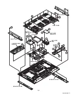
Page 98: ...1 6 No YA229B PACKING Page 3 34 FRONT FRONT FRONT FRONT 2 7 8 7 7 7 7 7 7 5 2 7 6 8 3 4 1 ...

Page 99: ...IC SERVICE INSTRUCTIONS Please refer to PD Z50DX4 No YA229 about this section SECTION 3 DISASSEMBLY Please refer to PD Z50DX4 No YA229 about this section SECTION 4 ADJUSTMENT Please refer to PD Z50DX4 No YA229 about this section SECTION 5 TROUBLESHOOTING Please refer to PD Z50DX4 No YA229 about this section ...

Page 100: ... No YA229B AV MULTIMEDIA COMPANY VIDEO DISPLAY CATEGORY 12 3 chome Moriya cho kanagawa ku Yokohama kanagawa prefecture 221 8528 Japan Victor Company of Japan Limited VPT Printed in Japan ...

Page 101: ...005 Victor Company of Japan Limited No YA229 2005 2 PDP COLOUR TELEVISION YA229 2004 12 PD Z50DX4 PD Z50DX4 S CD ROM No SML200502 BASIC CHASSIS FP2 TU Z50DX4 TU Z50DX4 S RECEIVER UNIT VM Z50DX4 VM Z50DX4 S PLASMA DISPLAY UNIT POWER ...

Page 102: ...Power Supply Type MM Metalized mylar capacitor PP Polypropylene capacitor MPP Metalized polypropylene capacitor MF Metalized film capacitor TF Thin film capacitor BP Bipolar electrolytic capacitor TAN Tantalum capacitor 3 Coils No unit Others µH As specified No indication Ceramic capacitor 2 Capacitors Capacitance value 1 or higher pF less than 1 µF Withstand voltage No indication DC50 V Others DC...

Page 103: ...CIRCUIT DIAGRAM 2 59 TEMP SENSOR PWB CIRCUIT DIAGRAM 2 60 DISPLAY SWITCH PWB CIRCUIT DIAGRAM 2 60 LINE FILTER PWB CIRCUIT DIAGRAM 2 61 PANEL SUB POWER PWB CIRCUIT DIAGRAM 2 63 PATTERN DIAGRAMS RECEIVER UNIT 2 65 RECEIVER PWB PATTERN 2 65 ANALOG SIGNAL PWB PATTERN 2 67 DIGITAL SIGNAL PWB PATTERN 2 69 REAR JACK PWB PATTERN 2 73 FRONT CONTROL PWB PATTERN 2 73 REGULATOR PWB PATTERN 2 75 SYSTEM POWER P...

Page 104: ...08A LCA10353 03D SFP 9312A RECEIVERPWB ANALOG SIGNAL PWB REAR JACK PWB DIGITAL SIGNAL PWB FRONTCONTROLPWB REGULATORPWB SYSTEMPOWERPWB DISPLAY INTERFACE PWB AUDIO PWB TEMP SENSOR PWB DISPLAY LED PWB DISPLAYSWITCH PWB LINEFILTER PWB SUBPOWERPWB PD Z50DX4 S LCA10428 42H SFP 0D308A LCA10426 14C SFP 9317A LCA10360 10E SFP 7308A LCA90143 14B SFP 9309A LCA10353 04D SFP 9313A No YA229 2 3 IC BOTTOM VIEW F...

Page 105: ...2 4 No YA229 ...

Page 106: ... BASE TEMP SENSOR PWB DVI MDA D D A A B SR CB SL E Q G 601 AH1 T FL FR X V PDP UNIT DISPLAY INTERFACE PWB V 1 Vs 2 Vs 3 Vs 4 NC 5 GND P13 P5 P4 P5 P6 P501 P502 P503 P504 P505 P506 P507 P100 P508 P509 P1 P10 P5 P6 P4 P510 P511 P16 P14 P15 P10 P2 P9 P5 P11 P3 P6 P300 P104 P105 P106 P101 P102 P103 9005 9001 9001 8001 805 806 8011 8009 P12 P1 P3 P5 P2 P6 P9 P3 P403 P402 P401 P7 P2 P407 P408 P7 P4 P406...

Page 107: ...VIDEO INPUT 3 V2 V L2 R2 L R INPUT 2 COMPONENT VIDEO CPB3 Cb CPR3 Cr CPY3 Y J2006 MONITOR REC OUT MON_V V MON_L MON_R L R MON_Y MON_C S VIDEO INPUT 2 INPUT 4 V3 V L3 R3 L R IC6101 DVI FORMAT CONVERSION ENCRYPTION TMDS_DATA 6 DIGITAL SIGNAL PWB DISPLAY UNIT RECEIVER UNIT J2002 INPUT 1 COMPONENT VIDEO CPB1 Cb CPR1 Cr CPY1 Y J2004 EUROL4 EUROR4 DIGITAL IN AUDIO ANALOG L_SWSUB R_SWSUB L_SWMAIN R_SWMAI...

Page 108: ...001 MSP3415D QGB3GHX QAU0366 002 QAU0366 001 OLLC05843 04 MSP3415G QGB8V3M TPS852 W QAU0366 002 NQR0389 003X CH CH CH NCF31AZ 105X NCF31AZ 105X NCF31AZ 105X NCF31AZ 105X CH CH CH NQR0389 003X MA8100 M X QAX0773 001Z 16 MA8100 M X MA8100 M X HA17558 AF X AMP HA17558 AF X HA17558 AF X 16 16 16 16 16 NQR0431 001X NQL79GM 4R7X 10 NRSA02J 0R0X 2SC3928A QR X BUFFER NRSA02J 0R0X NRSA02J 0R0X NRSA02J 0R0X...

Page 109: ... 16 OPEN OPEN OPEN OPEN OPEN NPN NPN NPN NPN NPN NPN PNP PNP PNP NPN NPN OPEN OPEN OPEN OPEN OPEN OPEN OPEN OPEN OPEN 0 OPEN OPEN OPEN OPEN 22k 47k 82k 15k 33k 220 10k 47k 27k 22k 47k 82k 15k 33k 220 10k 47k 22k 47k 82k 15k 33k 220 10k 47k 27k 0 0 2 2k 2 2k 5 6k 2 2k 2 2k 5 6k OPEN OPEN OPEN OPEN OPEN OPEN 10k OPEN 10k 10k OPEN OPEN 0 0 OPEN 10 50 OPEN OPEN OPEN OPEN OPEN 1 16 10 16 100 10 10 16 O...

Page 110: ...OPEN 0 1 0 OPEN OPEN OPEN OPEN OPEN OPEN 0 1 OPEN OPEN OPEN OPEN OPEN 0 1 OPEN OPEN OPEN OPEN OPEN 0 1 OPEN OPEN OPEN OPEN 0 1 OPEN OPEN OPEN OPEN 0 1 OPEN OPEN OPEN OPEN OPEN 0 OPEN OPEN OPEN OPEN OPEN 0 OPEN OPEN OPEN OPEN OPEN 0 OPEN OPEN OPEN OPEN OPEN 0 OPEN 1k OPEN OPEN OPEN 0 OPEN OPEN OPEN OPEN 0 OPEN OPEN 0 OPEN 0 0 OPEN 0 OPEN 0 0 100k OPEN 0 0 0 100 1k 0 OPEN OPEN 0 OPEN NPN OPEN OPEN O...

Page 111: ...k OPEN OPEN OPEN 10k OPEN OPEN OPEN OPEN 1k OPEN OPEN OPEN 10 25 OPEN OPEN OPEN 10 25 OPEN OPEN OPEN NPN OPEN OPEN OPEN OPEN 0 01 50 0 01 50 0 01 50 OPEN OPEN 1 16 OPEN OPEN 1 16 OPEN 0 0 OPEN OPEN OPEN OPEN OPEN OPEN 0 0 OPEN OPEN OPEN OPEN OPEN OPEN OPEN 0 0 OPEN 8 2k 330 2 2 0 01 OPEN OPEN OPEN 0 01 OPEN 10k OPEN 2 2k OPEN 0 0 1 50 OPEN 1 OPEN OPEN OPEN OPEN OPEN OPEN OPEN OPEN OPEN OPEN OPEN O...

Page 112: ...EN OPEN 0 1 16 OPEN OPEN OPEN OPEN OPEN 10 16 OPEN OPEN OPEN OPEN OPEN OPEN OPEN OPEN OPEN OPEN OPEN 1000p OPEN OPEN OPEN OPEN OPEN 10p OPEN OPEN OPEN OPEN OPEN 0 1 16 OPEN OPEN OPEN OPEN OPEN 0 1 16 OPEN OPEN OPEN OPEN OPEN 0 1 16 OPEN OPEN OPEN OPEN OPEN 0 1 16 OPEN OPEN OPEN OPEN OPEN 1000p OPEN OPEN OPEN OPEN OPEN 12p OPEN OPEN OPEN OPEN OPEN 10p OPEN OPEN OPEN OPEN OPEN OPEN OPEN OPEN OPEN OP...

Page 113: ...05106 11 OLLC05106 12 OLLC05106 13 OLLC05106 09 OLLC05106 10 NEX51CM 335X NQL52EM 220X NEX50JM 156X NQL52EM 220X 2SC3074 OY X NQL52EM 220X NEX51CM 335X 1 2W PTZ11B X PTZ6 8B X OPEN OPEN OPEN OPEN OPEN OPEN OPEN OPEN OPEN OPEN OPEN OPEN OPEN OPEN OPEN OPEN 0 47 16 47 16 47 16 47 16 0 OPEN 0 47 16 OPEN 47 16 OPEN 47 16 OPEN 47 16 OPEN 47 16 OPEN OPEN OPEN OPEN 330 OPEN 12V GND BS_ABT30 GND GND GND G...

Page 114: ... CB1 CB1 QNZ0699 001 UN2226 X UN2226 X UN2110 X QNN0641 001 GND GND GND GND GND GND GND GND GND GND S2 C2_RE2 Y2 V2 YS2 GR2 BU2 EU_SDA0 TVLINK GND GND S22 SLW2 L2 GND GND GND GND GND GND R2 CENTIN UD_ROUT UD_LOUT R3 L3 V3 SLOW3 CPR3 CPB3 CPY3 EUROR4 EUROL4 GND GND GND GND GND GND GND GND QGF0508F1 50X GND GND GND GND GND GND GND GND GND TV_LOUT TV_ROUT CPY1 GR1 CPB1 BU1 CPR1 RE1 D3_YS1 R1 GND GND ...

Page 115: ...N OPEN OPEN OPEN OPEN OPEN OPEN OPEN OPEN OPEN OPEN OPEN OPEN OPEN OPEN OPEN OPEN OPEN OPEN OPEN OPEN OPEN OPEN OPEN OPEN OPEN OPEN OPEN OPEN OPEN OPEN OPEN OPEN OPEN OPEN OPEN OPEN OPEN OPEN OPEN OPEN OPEN OPEN OPEN OPEN OPEN OPEN OPEN OPEN OPEN OPEN OPEN OPEN OPEN OPEN OPEN OPEN OPEN OPEN OPEN OPEN OPEN OPEN OPEN OPEN OPEN OPEN OPEN OPEN OPEN OPEN OPEN OPEN OPEN OPEN OPEN OPEN OPEN OPEN OPEN OPE...

Page 116: ...OLLC05355 06 NRSA02J 0R0X NRSA02J 0R0X NRSA02J 0R0X NRSA02J 0R0X NRSA02J 0R0X NRSA02J 0R0X NRSA02J 0R0X NRSA02J 0R0X NRSA02J 0R0X NRSA02J 0R0X NRSA02J 0R0X NRSA02J 0R0X NRSA02J 0R0X OLLC05355 29 NRSA02J 0R0X NRSA02J 0R0X NRSA02J 0R0X NRSA02J 0R0X NRSA02J 0R0X NRSA02J 0R0X NRSA02J 0R0X OLLC05355 30 OLLC05355 39 OLLC05355 03 OLLC05355 14 NRSA02J 0R0X NRSA02J 0R0X NRSA02J 0R0X NRSA02J 0R0X NRSA02J 0R...

Page 117: ...RZ0034 101W NRZ0034 101W NRZ0034 103W OLLC05355 39 NRZ0034 103W NRZ0034 103W NRZ0034 103W NRZ0034 103W MM1572FN X OLLC05355 32 OLLC05355 34 NRZ0034 103W NRZ0034 103W NRZ0034 103W NRZ0034 103W NRZ0034 103W NRZ0034 103W OLLC05355 41 OLLC05355 44 NRZ0034 103W NRZ0034 103W NRZ0034 103W NRZ0034 103W T B2 T T T T VDDPLL PLLIN VCOFIL VSSPLL VDDXO XOIN XOOUT VSSXO BUSSEL DVDD1 GRD9 GRD8 GRD7 DVSS12 GRD6 G...

Page 118: ... OPEN OPEN OPEN OPEN OPEN OPEN OPEN OPEN OPEN OPEN OPEN OPEN OPEN OPEN OPEN OPEN OPEN OPEN OPEN OPEN OPEN OPEN 0 OPEN OPEN OPEN OPEN 0 OPEN OPEN OPEN OPEN 0 OPEN OPEN OPEN OPEN 0 OPEN OPEN OPEN OPEN OPEN OPEN OPEN OPEN 0 OPEN OPEN OPEN OPEN OPEN OPEN OPEN OPEN OPEN OPEN OPEN OPEN OPEN OPEN OPEN OPEN OPEN OPEN OPEN OPEN OPEN OPEN OPEN OPEN OPEN OPEN OPEN 0 OPEN OPEN OPEN OPEN OPEN OPEN OPEN OPEN OP...

Page 119: ... NRS144J 0R0X NRS144J 0R0X OLLC05355 30 OLLC05355 39 CH OLLC05355 32 OLLC05355 34 OLLC05355 05 OLLC05355 OLLC05355 02 OLLC05355 06 OLLC05355 29 OLLC05355 03 OLLC05355 14 OLLC05355 08 OLLC05355 11 CH CH CH CH OLLC05355 41 OLLC05355 44 CH CH OLLC05355 30 OLLC05355 39 OLLC05355 32 OLLC05355 34 OLLC05355 05 OLLC05355 OLLC05355 02 OLLC05355 06 OLLC05355 29 OLLC05355 03 OLLC05355 14 OLLC05355 08 OLLC053...

Page 120: ...0R0W NRZ0034 0R0W NRZ0034 0R0W NRZ0034 0R0W NRZ0034 0R0W NRZ0034 0R0W NRZ0034 0R0W NRZ0034 0R0W NRZ0034 0R0W NRZ0034 0R0W NRZ0034 0R0W NRZ0034 0R0W NRZ0034 0R0W NRZ0034 0R0W NRZ0034 0R0W NRZ0034 0R0W NRZ0034 0R0W NRZ0034 0R0W NRZ0034 0R0W NRZ0034 0R0W NRZ0034 0R0W NRZ0034 0R0W SN74LVC 1G08V X SN74LVC 1G08V X NRZ0034 0R0W NRZ0034 0R0W NRZ0034 0R0W OLLC05355 41 CH CH OLLC05355 44 OLLC05355 30 OLLC05...

Page 121: ...N OPEN OPEN OPEN OPEN OPEN 0 1 16 0 1 16 0 1 16 0 1 16 0 1 16 OPEN 10 10 OPEN OPEN OPEN OPEN OPEN 1k 1k 0 100 100 100 OPEN 0 OPEN OPEN OPEN OPEN OPEN OPEN 0 1 16 OPEN OPEN OPEN OPEN OPEN OPEN OPEN OPEN OPEN 0 1 16 0 1 16 0 1 16 0 1 16 0 1 16 OPEN 10 10 OPEN OPEN OPEN OPEN 1k 1k 0 100 100 100 OPEN 0 OPEN OPEN OPEN 100 0 OPEN OPEN OPEN OPEN OPEN OPEN OPEN OPEN OPEN 100 0 OPEN OPEN OPEN OPEN OPEN OPE...

Page 122: ... OPEN OPEN OPEN OPEN OPEN OPEN OPEN OPEN OPEN OPEN OPEN OPEN OPEN OPEN OPEN OPEN OPEN OPEN OPEN OPEN OPEN OPEN OPEN OPEN OPEN OPEN OPEN OPEN OPEN OPEN OPEN OPEN OPEN OPEN OPEN OPEN OPEN OPEN OPEN OPEN OPEN OPEN OPEN OPEN OPEN OPEN OPEN OPEN OPEN OPEN OPEN OPEN OPEN OPEN OPEN OPEN OPEN OPEN OPEN OPEN OPEN OPEN OPEN OPEN OPEN OPEN OPEN OPEN OPEN OPEN OPEN OPEN OPEN OPEN OPEN OPEN OPEN OPEN OPEN OPEN...

Page 123: ...PEN OPEN OPEN OPEN OPEN OPEN OPEN OPEN OPEN OPEN OPEN OPEN OPEN OPEN OPEN OPEN OPEN OPEN OPEN OPEN OPEN OPEN OPEN OPEN OPEN OPEN OPEN OPEN OPEN OPEN OPEN OPEN OPEN OPEN OPEN OPEN OPEN OPEN OPEN OPEN OPEN OPEN OPEN OPEN OPEN OPEN OPEN OPEN OPEN OPEN OPEN OPEN OPEN OPEN OPEN OPEN OPEN OPEN OPEN OPEN OPEN OPEN OPEN OPEN OPEN OPEN OPEN OPEN OPEN OPEN OPEN OPEN OPEN OPEN OPEN OPEN OPEN OPEN OPEN OPEN O...

Page 124: ... OPEN OPEN OPEN OPEN OPEN 47k OPEN OPEN OPEN OPEN OPEN OPEN OPEN OPEN OPEN 27k OPEN 47k 100k 100k OPEN 33k 27k OPEN 150k OPEN 150k 150k 100k 33k OPEN OPEN OPEN 100k OPEN OPEN OPEN OPEN OPEN 22k OPEN OPEN OPEN 33k 33k 47k OPEN OPEN 47k OPEN OPEN OPEN OPEN OPEN OPEN OPEN 0 01 0 01 100 100 OPEN 0 OPEN OPEN OPEN OPEN OPEN OPEN OPEN OPEN OPEN OPEN OPEN OPEN OPEN OPEN OPEN 0 0 047 16 0 1 16 OPEN OPEN OP...

Page 125: ...OPEN 4 4 OPEN 4 5 4 4 OPEN 0 5 OPEN OPEN OPEN OPEN OPEN 2 OPEN OPEN 0 0 0 0 0 0 OPEN OPEN 0 1 16 OPEN 47K OPEN 47K 47K 0 0 0 OPEN OPEN OPEN OPEN OPEN OPEN OPEN OPEN OPEN OPEN OPEN OPEN OPEN 0 1 16 20k 22k 20k 10k OPEN 2 7k 10k 10k 10k 10k 4 7k 2200p 2200p 2200p OPEN OPEN OPEN OPEN OPEN OPEN OPEN OPEN OPEN OPEN 0 OPEN OPEN OPEN OPEN OPEN OPEN OPEN OPEN OPEN OPEN OPEN OPEN OPEN OPEN OPEN OPEN OPEN O...

Page 126: ...5V STB_5V POWERLED MECHA_SW HP_VOL HP_DET S2_4 S4_DET R4 L4 V4 Y4 C4 REC_LED SELSW1 SELSW2 GND GND PC_DET PC_R PC_G PC_B PC_HS PC_VS QGF0508F1 50X QSW0619 003Z F L R DET GND NRS181J 0R0X QNZ0061 001 PC IN QNZ0438 001 QSW0619 003Z QSW0619 003Z QNZ0438 001 QNZ0438 001 QNZ0438 001 QSW0619 003Z QNZ0438 001 QSW0619 003Z QSW0619 003Z 16 50 50 16 OLLC05783 SMLU12E16W P NRSA63J 0R0X SMLU12E16W P NRSA63J 0...

Page 127: ... MA111 X MP1580HS X NQL71EM 150X NRSA02J 0R0X 3D 3D NRSA02J 0R0X NRSA02J 0R0X 3D 3D NQL52EM 220X MP1580HS X PQ20WZ11 X D1FS4 X D1FS4 X MA111 X UN2213 X NEHM1EM 336X NEHM1EM 336X NRSA63D 183X NRSA63D 682X NRSA63D 103X PQ20WZ11 X D1FS4 X NEHM1CM 476X NEHM1CM 476X NRSA63D 332X M X MA8051 NRSA02J 0R0X OLLC05108 12 NRSA02J 0R0X NRSA02J 0R0X 3D MP1580HS X MP1580HS X MP1410ES X PQ20WZ11 X D1FS4 X D1FS4 X...

Page 128: ...T AC110V AC240V 50Hz 60Hz 630V QFP32JK 332 RGP10J 5025 T3 1 2W 25 QECQ1EM 228 50 CH 2W MA8024 X 2KV 50 1W QQL26AK 220Z RGP10J 5025 T3 400 QEZ0199 127 400VAC QCZ9079 102 25 QUY160 075Y SARS01 T2 D1FL20U X 100 D2SBA60 UTCTL431 T 25 QECQ1EM 228 RD33E B1 T2 50 QQR1139 001 S1WB A 60 X 2SD1266A QP MA8091 L X MA8091 L X MA8024 X NRSA02J 0R0X UN2213 X UN2213 X 2kv 1N4002G T2 QGA2501C5 03Z OPEN OPEN REGULA...

Page 129: ...LLC04083 02 OLLC04083 OLLC04083 03 OLLC04083 04 HD6433 684A27H HD6433 684A27H HD64F 3687A80H HD64F 3687A80H OLLC04083 02 OLLC04083 OLLC04083 03 OLLC04083 04 TC74VHCT 541AFTX TC74VHCT 541AFTX CD74HC 4053PW X CD74HC 4053PW X OLLC04083 06 OLLC04083 07 OLLC04083 06 HD64F 3687B04H OLLC04083 07 HD64F 3687A80H OLLC04083 06 OLLC04083 07 OLLC04083 02 OLLC04083 OLLC04083 03 OLLC04083 04 OLLC04083 06 OLLC040...

Page 130: ... OPEN OPEN OPEN 1k 0 0 1k 1k 1k OPEN OPEN OPEN OPEN OPEN OPEN OPEN OPEN 1k OPEN OPEN OPEN OPEN OPEN OPEN 1k 0 100 100 1k 1k 0 OPEN 0 0 0 100 2 2k 2 2k OPEN OPEN OPEN OPEN OPEN OPEN OPEN OPEN OPEN OPEN 100 OPEN OPEN OPEN OPEN OPEN OPEN NRZ0 NRZ0 OPEN OPEN OPEN NRZ0 NRZ0 NRZ0 OPEN OPEN OPEN NRZ0 NRZ0 NRZ0 15k 5 6k OPEN OPEN OPEN 0 OPEN NRZ0 NRZ0 OPEN OPEN OPEN 0 1 OPEN NRZ0 NRZ0 OPEN OPEN OPEN NRZ0 ...

Page 131: ... 16 16 16 CB CB 16 CB QGA2001C2 03V QGA2001C2 03V QGA2001C2 02V BA05FP X OLLC04083 03 OLLC04083 04 PQ20WZ11 X QGA2001C2 03V QGA2001C2 03V QGA2001C2 03V QGA2001C2 02V BA05FP X OLLC04083 02 OLLC04083 OLLC04083 06 OLLC04083 03 OLLC04083 04 OLLC04083 07 PQ20WZ11 XPQ20WZ11 X QGA2001C2 03V QGA2001C2 03V QGA2001C2 03V QGA2001C2 03V QGA2001C2 03V QGA2001C2 03V QGA2001C2 02V QGA2001C2 02V OLLC04083 06 OLLC...

Page 132: ...X QRJ146J 2R2X QFV21HJ 124Z QFV21HJ 124Z QRJ146J 2R2X QRJ146J 2R2X QFV21HJ 124Z QFV21HJ 124Z MA8330 M X MA8330 M X MA8330 M X MA8330 M X MA8330 M X MA8330 M X MA8330 M X MA8330 M X CH 25 CB1 25 CB1 CH CH 25 CB1 QGA2501C5 03Z CB2 QGA2501C5 06Z 50 50 OLLC07153 MA111 X MA111 X MA111 X QETM1EM 228 WJK0050 010A D1FS4 X CB2 CH OLLC07153 02 25 CB1 QJK016 061001 QJK016 080703 QETM1CM 478 QETM1CM 478 QETM1...

Page 133: ...GND IC8101 R8101 R8102 C8101 CN800V R8103 TCN75 5 0MOA X PS QGA2001C1 04 100 100 0 1 10k GND GND GND R2703 S2702 S2705 S2706 S2704 S2701 POWER R2701 R2702 R2704 S2703 S2707 CN000T QSW0619 003Z QSW0619 003Z QSW0619 003Z QSW0619 003Z QSW0619 003Z QSW0619 003Z QSW0619 003Z QGA2501F1 06 5 6k 5 6k 15k 15k GND GND GND DISPLAY SWITCH PWB ASS Y LCA90148 07C SFP 0L367A MENU ASPECT CH VOL VOL INPUT CH DISPL...

Page 134: ... WJK0050 008A WJK0050 009A QFZ9075 224 QUB070 26FPHM WJK0050 009A OLLC02729 12 QMCB006 C01 QQR1376 001 QQR1376 001 QCZ9079 102 QCZ9079 102 QQR1281 002 QFZ9075 224 QUB070 26FPHM WJK0050 009A OLLC02729 13 QMCB006 C01 QQR1281 002 OLLC02729 14 QFZ9075 224 QUB070 26FPHM WJK0050 008A QNC0099 001 QQR1281 002 OLLC02729 15 QMCB006 C01 QNC0099 001 QFZ9075 224 QMCB006 C01 QMCB006 C01 QUB070 26FPHM WJK0050 00...

Page 135: ... N50 Y QRA14CF 8201Y QCZ9079 102 QCZ9079 102 QRA14CF 2001Y PS SARS01 T2 QRZ9017 470 PC123Y22FZ QRL01EJ 104X QRL01EJ 104X 1 2W 1W 630V QFP32JK 332 3W QRL03EJ 220X QUY160 100Y PS2581AL1 QW QRL029J 104 QUY160 100Y QRL029J 104 QRL039J 220 OLLC04305 1 2W OLLC04305 02 QCZ0354 471Z PC123Y22FZ QCZ0340 471 QRL01EJ 104X QRL03EJ 181X 50 QRL039J 181 QRL01EJ 104X QRL03EJ 220X OLLC04305 03 25 QECQ1EM 228 CH QCZ...

Page 136: ...C3518 R3102 C3523 C3546 C3547 C3520 C3524 C3526 C3527 R3103 C3531 C3544 R3601 C3534 C3535 C3537 C3540 C3545 C3541 C3522 D3003 D3004 D3501 CL3002 R3002 R3006 R3008 L3501 R3015 R3016 R3502 R3503 R3505 R3506 R3516 Q3503 R3001 R3005 R3003 R3517 R3007 R3010 R3011 R3009 R3541 Y3501 R3542 R3504 R3543 R3545 R3507 R3508 R3518 R3510 R3511 R3509 R3519 Y3502 R3546 R3547 R3501 R3104 R3544 C3007 R3540 C3010 C35...

Page 137: ...406 R407 RB203 RB501 RB512 RB801 RB802 Y904 DB301 DB302 R663 R664 R665 R666 R667 RB517 RB625 R671 R672 R673 R674 Q603 Q604 IC605 C911 C913 R907 IC401 C302 CB611 CB612 QB611 C306 C307 C308 C309 C310 C322 C323 C343 C346 C349 C401 C402 C501 C502 C503 C504 C505 C506 C508 C509 C510 C601 C602 C603 C604 C605 C606 C607 C608 C609 C610 C611 C612 C614 QB612 RB301 RB302 RB612 RB613 RB614 C667 C668 C669 C670 C...

Page 138: ...2 Q1533 Q1534 Q3001 Q3002 Q3003 Q3004 Q6501 Q7201 Q7202 Q7203 Q7204 Q7205 Q7206 Q7207 Q7208 Q7209 Q7401 Q7402 Q7501 Q7508 Q8002 Q8003 Q8004 R0105 R0106 R0107 R0109 R0110 R0116 R0117 R0119 R0120 R0121 R0122 R0125 R0126 R0127 R0128 R0129 R0131 R0132 R0133 R0134 R0136 R0137 R0138 R0139 R0140 R0141 W B R0512 R1001 R1002 R1003 R1004 R1005 R1006 R1007 W C R1010 R1011 R1014 R1016 R1101 R1102 R1104 R1105 ...

Page 139: ...69 R3070 R3071 R3072 R3089 R3094 R3095 R3096 R3097 R3098 R3099 R3100 R3101 R3102 R3103 R3107 R3112 R3113 R3114 R3115 R3116 R3117 R3118 R3119 R3120 R3122 R3123 R3124 D9204 R3126 R3207 R4004 R4005 R4006 R4007 R4008 R4015 R4016 R4018 R4019 R4022 R4023 R4024 R4025 R4026 R4027 R4028 R4035 R4037 R4039 R4041 R4042 R4043 R4044 R4045 R4046 R4047 R4048 R4049 R4050 R4051 R4052 R4053 R4054 R4056 R4057 R4058 R...

Page 140: ...60 C2261 C2262 C2263 C2264 R1505 J1101 R1206 R1207 C1001 C1002 C1003 C1004 C1009 C1102 C1106 C1107 D1001 D1101 D1102 D1103 D1104 D1105 D1201 D1301 D1302 D1303 D1304 J1001 J1301 J1302 Q1201 Q1202 Q1203 R1001 R1002 R1003 R1004 R1005 R1006 R1007 R1008 R1009 R1010 R1011 R1101 R1102 R1103 R1104 R1105 R1201 R1202 R1202 R1203 R1204 R1204 R1205 R1301 R1302 R1303 R1304 S1201 LC1401 C1014 LC1402 LC1403 R101...

Page 141: ...9204 R9205 R9206 R9207 R9208 R9231 R9401 R9402 R9403 R9404 R9405 R9406 R9407 R9421 R9422 R9423 R9424 R9425 R9426 R9427 R9601 R9602 R9603 R9604 R9605 R9606 R9607 R9609 R9610 R9611 R9612 R9621 R9622 R9623 R9624 R9625 R9626 R9627 R9821 R9822 R9823 R9824 Y9401 Y9402 Y9601 Y9602 R96 29 R9630 C9802 C9803 C9431 C9213 C9234 C9404 C9424 C9604 C9624 C9801 D9211 D9233 D9403 D9423 D9602 D9622 D9801 D9823 IC92...

Page 142: ...6 R9207 R9208 R9313 RY9001 SG9001 T9001 VA9002 Y9002 Y9003 Y9201 H9015 R9040 R9209 D9351 CP9202 R9036 Y9007 D9023 Q9001 Q9351 C9351 R9037 R9038 R9039 Y90 04 C9352 CN9601 R9351 Y9011 C9353 D9211 D9212 D9352 D9353 D9354 D9355 Q9352 Q9353 R9352 H9001 D9024 Y9001 R9001 C9007 C9024 C9205 C9031 C9029 K9001 D9011 D9010 D9002 D9017 F9001 D9001 D9016 D9201 D9015 IC9202 VA9001 R9005 R9007 R9012 Y9006 R9013 ...

Page 143: ...02 R603 R935 R936 R937 R938 R628 D611 R624 R801 R802 R803 R804 R805 R810 R811 R812 R813 R822 R823 R829 R830 R833 R839 R840 R842 R843 R854 R856 R884 R885 R888 R889 R890 R891 R893 R894 R899 R900 R902 R914 R915 R916 R917 R941 R942 R626 R627 R102 C103 C105 R109 Q805 Q806 Q807 R101 R103 R943 R108 Q811 C621 C622 C623 C624 C625 C626 R606 R608 R609 R612 K805 R607 R610 R615 R636 R637 R939 RA613 RA614 RA615...

Page 144: ...R513 R514 R525 R526 R527 R528 R529 R530 R531 R532 R601 IC601 C830 F R618 R619 R621 R622 R806 R807 R808 R809 R814 R815 R816 R817 R818 R819 R820 R821 R824 R827 R828 R837 R838 R844 R845 R846 R847 R848 R8 49 R850 R851 R852 R853 R855 R857 R858 R859 R861 R863 R864 R865 R866 R867 R868 R869 R870 R871 R872 R873 R874 R875 R876 R877 R878 R879 R880 R881 R882 R883 R886 R887 R892 R895 R896 R897 R898 R901 R904 R...

Page 145: ...R6616 Y6627 Y6628 Y6629 Y6630 Y6631 Y6632 Y6633 Y6634 C6605 C6560 C6561 C6562 C6563 C6564 C6565 C6566 C6567 C6568 C6569 C6570 D6501 D6502 D6503 D6504 D6505 D6506 Q6535 Q6536 R6561 R6562 R6563 R6564 R6567 R6568 R6569 R6570 R6577 R6578 R6579 R6580 R6585 R6586 R6587 R6588 C6514 C6515 C6516 C6517 C6518 C6576 C6577 C6578 C6581 C6582 C6583 C6584 C6588 C6695 C6696 D6551 IC6572 R6544 R6545 R6546 R6547 R66...

Page 146: ... R9302 R9303 T9001 C9011 W9012 R9013 W9008 W9006 W9010 W9007 W9014 W9018 Y9303 W9017 W9015 W9011 W9016 W9009 W9001 W9004 W9003 W9002 W9005 Y9901 Y9304 C9901 C9904 C9911 C9912 C9913 C9914 C9915 C9916 C9917 E2 E3 PW F9901 J9901 K9901 K9902 LF9901 LF9902 LF9903 LF9904 R9901 R9902 R9903 VA9901 Y9901 Y9902 Y9903 Y9904 Y9905 Y9906 Y9907 Y9908 Y9909 Y9910 Y9911 Y9912 Y9913 Y9914 Y9915 Y9916 Y9917 Y9918 F...

Page 147: ...9 31 3 10 4 8 11 4 7 12 4 7 13 0 14 0 20 0 21 1 7 22 4 8 23 0 7 24 2 3 25 0 26 2 3 27 2 3 28 0 TU3101 1 31 3 2 4 8 3 4 5 4 4 5 5 2 4 6 0 13 3 7 14 4 8 15 4 5 16 2 8 17 0 18 0 7 19 0 6 20 0 5 21 4 8 22 0 23 8 9 24 4 2 25 4 1 26 0 IC2002 1 3 3 2 0 3 0 4 1 9 5 3 3 6 0 7 0 8 4 8 Q2101 E 1 0 C 0 B 0 2 Q2102 E 1 4 C 0 B 0 6 CN005 1 0 2 0 3 0 4 2 9 5 0 6 0 7 0 8 30 6 9 0 10 0 11 15 9 12 0 13 7 0 14 7 1 1...

Page 148: ...2 40 1 2 41 1 2 42 1 2 43 0 44 3 3 45 1 1 46 1 3 47 1 1 48 1 3 49 0 50 1 0 51 0 9 52 0 8 53 0 54 0 8 55 0 6 56 0 2 IC602 1 3 3 2 0 3 0 4 0 5 0 6 0 7 0 8 0 9 3 3 10 0 11 0 12 0 13 0 14 0 15 0 16 0 17 0 18 0 19 0 20 0 21 0 22 0 23 0 24 0 25 1 6 26 3 2 27 3 3 28 3 2 29 0 30 2 8 31 1 5 32 3 3 33 0 34 3 3 35 0 36 0 37 0 38 0 39 1 4 40 0 41 1 1 42 1 3 43 0 44 0 45 0 46 2 5 47 0 48 0 49 0 50 0 51 0 52 0 ...

Page 149: ... 1 5 SHEET2 ANALOG SIGNAL PWB 2 5 SHEET3 ANALOG SIGNAL PWB 3 5 IC1531 22 0 3 Vp p H IC1531 23 0 3 Vp p H DIGITAL SIGNAL PWB 1 11 SHEET8 DIGITAL SIGNAL PWB 10 11 SHEET17 IC1531 79 0 8 Vp p H TU3101 16 0 9 Vp p H IC801 3 2 0 Vp p IC801 1 0 9 Vp p H IC201 19 3 2 Vp p H IC7001 78 3 2 Vp p V IC201 29 3 0 Vp p V IC7001 23 2 2 Vp p 0 5µs IC1531 13 3 4 Vp p 1µs IC1531 28 4 5 Vp p 0 5µs IC1531 30 1 5 Vp p ...

Page 150: ... No YA229 AV MULTIMEDIA COMPANY VIDEO DISPLAY CATEGORY 12 3 chome Moriya cho kanagawa ku Yokohama kanagawa prefecture 221 8528 Japan Victor Company of Japan Limited VPT Printed in Japan ...

Page 151: ...pacitor MF R Metal Film Resistor MF CAP Metalized Film Capacitor MG R Metal Glazed Resistor MM CAP Metalized Mylar Capacitor MP R Metal Plate Resistor MP CAP Metalized Polystyrol Capacitor OM R Metal Oxide Film Resistor PP CAP Polypropylene Capacitor CMF R Coating Metal Film Resistor PS CAP Polystyrol Capacitor UNF R Non Flammable Resistor TF CAP Thin Film Capacitor CH V R Chip Variable Resistor M...

Page 152: ...ISPLAY LED PW BOARD ASS Y LCA90175 05B SFP 0L269A 15 DISPLAY SWITCH PW BOARD ASS Y LCA90148 07C SFP 0L367A 15 REMOTE CONTROL UNIT PARTS LIST RM C1830 1C 16 PACKING PARTS LIST 16 PACKING 17 RECEIVER UNIT TU Z50DX4 TU Z50DX4 S USING P W BOARD 18 EXPLODED VIEW PARTS LIST 18 EXPLODED VIEW 19 PRINTED WIRING BOARD PARTS LIST TU Z50DX4 20 FRONT CONTROL PW BOARD ASS Y LCA10466 04B SFP 8302A 20 REGULATOR P...

Page 153: ...CREW M4 x 16mm x22 3 LC11721 004A REAR COVER 4 LC21782 001A 0L RATING LABEL VM Z50DX4 4 LC21782 002A 0L RATING LABEL VM Z50DX4 S 5 LC41693 001A CAUTION LABEL 6 LC41610 002A TERMINAL LABEL 7 LC41694 001A INLET LABEL 8 QYSBSFG4012MA TAP SCREW M4 x 12mm x8 9 LC11722 001A BACK COVER R 10 LC11722 002A BACK COVER L 11 LC11717 002D SPEAKER HOLDER L 12 LC42065 001A SCREW x2 13 LC42067 001A SCREW x5 14 LC1...

Page 154: ...3 4 No YA229 EXPLODED VIEW 1 TERMINAL COVER CHASSIS SHIELD BRACKET CHASSIS BASE 13 13 12 13 13 14 13 17 18 16 11 4 5 1 8 9 8 10 2 1 7 6 3 15 201 200 202 100 101 102 18 ...

Page 155: ...5 LC32525 001A WIRE BRACKET 46 QYSBSFG4012ZA TAP SCREW M4 x 12mm 47 LC11749 001C WOOFER SPEAKER HOLDER ASSY 48 LC32433 001B BRAND PLATE 49 QQR0675 001 CORE FILTER x2 203 LCA10353 03D SUB POWER PWB VM Z50DX4 203 LCA10353 04D SUB POWER PWB VM Z50DX4 S 204 LCA90146 06B TEMP SENSOR PWB 205 LCA90148 07C DISPLAY SWITCH PWB 206 LCA90175 05B DISPLAY LED PWB 300 QLE0036 001 PDP UNIT Inc No 301 311 301 LG 6...

Page 156: ... 2 GAS insertion hole POWER CHASSIS PWB BACK BRACKET FAN BRACKET 30 31 31 203 32 303 302 204 301 307 306 308 311 205 206 305 310 309 300 304 33 34 35 37 36 38 36 39 40 41 42 44 47 48 42 44 43 45 46 43 34 34 33 34 49 49 39 40 39 ...

Page 157: ...t Name Description Local 60 LC32466 001A SPACER x2 61 LC32466 002A SPACER x2 62 LC32467 001B FRONT FILTER VM Z50DX4 62 LC32655 001A FRONT FILTER VM Z50DX4 S 63 LC11712 004A FRONT PANEL SIDE FRAME SIDE FRAME TOP FRAME BOTTOM FRAME FILTER BRACKET FILTER BRACKET 61 60 60 61 62 63 ...

Page 158: ...1EM 476Z E CAPACITOR 47uF 25V M C6559 QETN1CM 107Z E CAPACITOR 100uF 16V M C6561 QETN1HM 105Z E CAPACITOR 1uF 50V M C6562 QETN1HM 225Z E CAPACITOR 2 2uF 50V M C6563 NCB31HK 104X C CAPACITOR 0 1uF 50V K C6564 NCB31HK 104X C CAPACITOR 0 1uF 50V K C6565 NCB31HK 104X C CAPACITOR 0 1uF 50V K C6566 NCB31HK 104X C CAPACITOR 0 1uF 50V K C6567 NCB11EK 105X C CAPACITOR 1uF 25V K C6568 NCB11EK 105X C CAPACIT...

Page 159: ...1 16W J R6609 NRSA63J 272X MG RESISTOR 2 7kΩ 1 16W J R6610 NRSA63J 333X MG RESISTOR 33kΩ 1 16W J R6611 NRSA63J 222X MG RESISTOR 2 2kΩ 1 16W J R6612 NRSA63J 333X MG RESISTOR 33kΩ 1 16W J R6613 NRSA63J 272X MG RESISTOR 2 7kΩ 1 16W J R6614 NRSA63J 333X MG RESISTOR 33kΩ 1 16W J R6615 NRSA63J 222X MG RESISTOR 2 2kΩ 1 16W J R6616 NRSA63J 333X MG RESISTOR 33kΩ 1 16W J R6617 NRSA63J 0R0X MG RESISTOR 0Ω 1 ...

Page 160: ...Ω 1 16W J R515 NRSA63J 102X MG RESISTOR 1kΩ 1 16W J Ref No Part No Part Name Description Local R517 NRSA63J 0R0X MG RESISTOR 0Ω 1 16W J R518 NRSA63J 153X MG RESISTOR 15kΩ 1 16W J R519 NRSA63J 562X MG RESISTOR 5 6kΩ 1 16W J R525 NRSA63J 0R0X MG RESISTOR 0Ω 1 16W J R526 NRSA63J 0R0X MG RESISTOR 0Ω 1 16W J R528 NRSA63J 0R0X MG RESISTOR 0Ω 1 16W J R529 NRSA63J 102X MG RESISTOR 1kΩ 1 16W J R532 NRSA63J...

Page 161: ...TOR 0Ω 1 16W J R940 NRSA63J 0R0X MG RESISTOR 0Ω 1 16W J R942 NRSA63J 101X MG RESISTOR 100Ω 1 16W J R943 NRSA63J 101X MG RESISTOR 100Ω 1 16W J R953 NRSA63J 473X MG RESISTOR 47kΩ 1 16W J R963 NRSA63J 153X MG RESISTOR 15kΩ 1 16W J R964 NRSA63J 104X MG RESISTOR 100kΩ 1 16W J R965 NRSA63J 562X MG RESISTOR 5 6kΩ 1 16W J R967 NRSA63J 0R0X MG RESISTOR 0Ω 1 16W J R968 NRSA63J 0R0X MG RESISTOR 0Ω 1 16W J R9...

Page 162: ... 123Y C RESISTOR 12kΩ 1 4W J R9055 QRA14CF 8201Y CMF RESISTOR 8 2kΩ 1 4W F R9057 QRA14CF 2001Y CMF RESISTOR 2kΩ 1 4W F R9058 QRE141J 273Y C RESISTOR 27kΩ 1 4W J R9059 QRE141J 102Y C RESISTOR 1kΩ 1 4W J T9001 QQS0247 001 SW TRANSF CP9001 QMFZ043 5R0Z J1 FUSE 5A AC250V CP9051 ICP N50 Y IC PROTECTOR 2 0A PC9001 PC123Y22FZ PHOTO COUPLER Ref No Part No Part Name Description Local IC1642 GP1UA261XK IR D...

Page 163: ...TOR 0 1uF 16V Z C610 NCF31CZ 104X C CAPACITOR 0 1uF 16V Z C611 NCF31CZ 104X C CAPACITOR 0 1uF 16V Z C612 NCF31CZ 104X C CAPACITOR 0 1uF 16V Z C621 NCF31CZ 104X C CAPACITOR 0 1uF 16V Z C622 NCF31CZ 104X C CAPACITOR 0 1uF 16V Z C623 NCF31CZ 104X C CAPACITOR 0 1uF 16V Z C624 NCF31CZ 104X C CAPACITOR 0 1uF 16V Z C625 NCF31CZ 104X C CAPACITOR 0 1uF 16V Z C626 NCF31CZ 104X C CAPACITOR 0 1uF 16V Z C802 N...

Page 164: ... J R873 NRSA63J 101X MG RESISTOR 100Ω 1 16W J R875 NRSA63J 101X MG RESISTOR 100Ω 1 16W J Ref No Part No Part Name Description Local R877 NRSA63J 0R0X MG RESISTOR 0Ω 1 16W J R878 NRSA63J 101X MG RESISTOR 100Ω 1 16W J R879 NRSA63J 103X MG RESISTOR 10kΩ 1 16W J R880 NRSA63J 472X MG RESISTOR 4 7kΩ 1 16W J R881 NRSA63J 221X MG RESISTOR 220Ω 1 16W J R882 NRSA63J 101X MG RESISTOR 100Ω 1 16W J R883 NRSA63...

Page 165: ...IODE D9005 1SS133 T2 SI DIODE D9006 RGP10J 04TS T3 SI DIODE D9008 SARS01 T2 SI DIODE D9009 SARS01 T2 SI DIODE D9011 1SS133 T2 SI DIODE D9051 FMX 22S SI DIODE D9052 RU3YX LFC4 SI DIODE C9001 QEZ0674 476 E CAPACITOR 47uF 450V M C9002 QFP32JK 332 PP CAPACITOR 3300pF 630V K C9003 QCZ0354 471Z C CAPACITOR 470pF 2kV K C9004 QCS31HJ 471Z C CAPACITOR 470pF 50V J C9006 QCB31HK 562Z C CAPACITOR 5600pF 50V K...

Page 166: ...K 2m BLACK 15 QMPB560 180 JC POWER CORD JP 1 8m BLACK VM Z50DX4 15 QMPB320 180 R POWER CORD JP 1 8m BLACK VM Z50DX4 S 16 QPA02503505P POLY BAG 25cm x 35cm 17 LCT1667 001A CAUTION BOOK English French Russian Arabic Chinese Persian 18 LCT1781 001A INST BOOK English 19 LCT1782 001A INST BOOK French Russian Arabic Chinese Persian 20 LCT1814 001A INST SHEET English French Russian Arabic Chinese Persian...

Page 167: ... No YA229 3 17 PACKING FRONT 1 9 8 4 5 3 7 6 29 26 27 29 29 29 26 3 2 11 12 13 22 23 25 24 10 21 17 18 20 19 16 28 14 15 ...

Page 168: ...8mm x2 13 LC42135 001A SERVICE COVER 14 QNB0036 001 HEX SCREW x2 15 QMCB004 001 AC INLET 16 LC21578 003A BACK COVER 17 QQR0491 001 FERRITE CORE 18 LC41284 002A FOOT x4 19 LC21782 001A 0L RATING LABEL TU Z50DX4 19 LC21782 002A 0L RATING LABEL TU Z50DX4 S 20 LC42063 001A SCREW x2 21 LC11747 001B BOTTOM CASE 22 LC11746 001B CHASSIS BASE 23 QUQ105 5013AE FFC WIRE 50pin 13cm 24 QUQ105 3004AA FFC WIRE 3...

Page 169: ... YA229 3 19 EXPLODED VIEW 103 19 18 a c d a b c d f b f DIGITAL HOLDER 1 1 1 2 24 25 26 28 27 3 5 4 23 22 29 21 16 17 7 14 13 12 11 7 8 9 6 15 6 101 201 200 102 101 302 100 303 304 305 300 301 306 10 20 8 ...

Page 170: ...63J 333X MG RESISTOR 33kΩ 1 16W J R1502 NRSA63J 333X MG RESISTOR 33kΩ 1 16W J R1503 NRSA63J 333X MG RESISTOR 33kΩ 1 16W J R1504 NRSA63J 333X MG RESISTOR 33kΩ 1 16W J R1505 NRSA63J 0R0X MG RESISTOR 0Ω 1 16W J CN800F QGF0508F1 50X CONNECTOR FFC FPC 1 50 J1001 QNS0051 001 3 5 JACK HEADPHONE J1101 QNZ0438 001 AV JACK VIDEO 4 IN J1401 QNZ0061 001 D CONNECTOR PC IN S1201 QSW0619 003Z TACT SWITCH POWER S...

Page 171: ...TOR 3 3kΩ 1 16W J R9031 NRSA63J 223X MG RESISTOR 22kΩ 1 16W J R9032 NRSA63J 333X MG RESISTOR 33kΩ 1 16W J R9033 NRSA63J 104X MG RESISTOR 100kΩ 1 16W J R9034 NRSA63J 682X MG RESISTOR 6 8kΩ 1 16W J R9035 NRSA63J 822X MG RESISTOR 8 2kΩ 1 16W J R9037 NRSA63J 470X MG RESISTOR 47Ω 1 16W J R9038 NRSA63J 332X MG RESISTOR 3 3kΩ 1 16W J R9039 NRSA63J 0R0X MG RESISTOR 0Ω 1 16W J R9202 NRS12BJ 333W MG RESISTO...

Page 172: ... 330X C CAPACITOR 33pF 50V J C874 NDC31HJ 150X C CAPACITOR 15pF 50V J Ref No Part No Part Name Description Local C875 NDC31HJ 100X C CAPACITOR 10pF 50V J C876 NCB31HK 103X C CAPACITOR 0 01uF 50V K C877 NCB31HK 103X C CAPACITOR 0 01uF 50V K C878 NCB31HK 104X C CAPACITOR 0 1uF 50V K C879 NCB31HK 104X C CAPACITOR 0 1uF 50V K C880 NEHL1AM 107X E CAPACITOR 100uF 10V M C881 NEHL1AM 107X E CAPACITOR 100u...

Page 173: ...G RESISTOR 2 2kΩ 1 16W J R840 NRSA63J 101X MG RESISTOR 100Ω 1 16W J R851 NRSA63J 391X MG RESISTOR 390Ω 1 16W J R852 NRSA63J 391X MG RESISTOR 390Ω 1 16W J R853 NRSA63J 183X MG RESISTOR 18kΩ 1 16W J R854 NRSA63J 822X MG RESISTOR 8 2kΩ 1 16W J R855 NRSA63J 682X MG RESISTOR 6 8kΩ 1 16W J R856 NRSA63J 105X MG RESISTOR 1MΩ 1 16W J R859 NRSA63J 821X MG RESISTOR 820Ω 1 16W J R860 NRSA63J 101X MG RESISTOR ...

Page 174: ...ODE D7501 RB501V 40 X SB DIODE D7502 MA111 X SI DIODE D9001 EC30HA03L X SB DIODE D9003 PTZ3 9B X Z DIODE D9101 EC30HA03L X SB DIODE D9102 EC30HA03L X SB DIODE D9103 PTZ3 9B X Z DIODE D9104 MA111 X SI DIODE D9201 EC30HA03L X SB DIODE D9203 PTZ3 9B X Z DIODE D9204 MA111 X SI DIODE C0103 NDC31HJ 330X C CAPACITOR 33pF 50V J C0105 NDC31HJ 270X C CAPACITOR 27pF 50V J C0107 NCF31CZ 104X C CAPACITOR 0 1uF...

Page 175: ... CAPACITOR 0 1uF 16V Z C3071 NCF31CZ 104X C CAPACITOR 0 1uF 16V Z Ref No Part No Part Name Description Local C3072 NCF31CZ 104X C CAPACITOR 0 1uF 16V Z C3074 NCF31CZ 104X C CAPACITOR 0 1uF 16V Z C3076 NCF31CZ 104X C CAPACITOR 0 1uF 16V Z C3097 NCB30JK 225X C CAPACITOR 2 2uF 6 3V K C3101 NCB30JK 225X C CAPACITOR 2 2uF 6 3V K C3105 NCB30JK 225X C CAPACITOR 2 2uF 6 3V K C3107 NCB31HK 103X C CAPACITOR...

Page 176: ...MG RESISTOR 1kΩ 1 16W J Ref No Part No Part Name Description Local R0129 NRSA63J 103X MG RESISTOR 10kΩ 1 16W J R0131 NRSA63J 472X MG RESISTOR 4 7kΩ 1 16W J R0132 NRSA63J 472X MG RESISTOR 4 7kΩ 1 16W J R0133 NRSA63J 0R0X MG RESISTOR 0Ω 1 16W J R0134 NRSA63J 472X MG RESISTOR 4 7kΩ 1 16W J R0137 NRSA63J 151X MG RESISTOR 150Ω 1 16W J R0138 NRSA63J 101X MG RESISTOR 100Ω 1 16W J R0140 NRSA63J 182X MG RE...

Page 177: ...ESISTOR 51Ω 1 16W J R3097 NRSA63J 510X MG RESISTOR 51Ω 1 16W J R3098 NRSA63J 510X MG RESISTOR 51Ω 1 16W J Ref No Part No Part Name Description Local R3099 NRSA63J 510X MG RESISTOR 51Ω 1 16W J R3100 NRSA63J 510X MG RESISTOR 51Ω 1 16W J R3101 NRSA63J 510X MG RESISTOR 51Ω 1 16W J R3102 NRSA63J 510X MG RESISTOR 51Ω 1 16W J R3103 NRSA63J 510X MG RESISTOR 51Ω 1 16W J R3104 NRSA63J 510X MG RESISTOR 51Ω 1...

Page 178: ...SISTOR 10kΩ 1 16W J R7048 NRSA63J 103X MG RESISTOR 10kΩ 1 16W J Ref No Part No Part Name Description Local R7049 NRSA63J 0R0X MG RESISTOR 0Ω 1 16W J R7057 NRSA63J 103X MG RESISTOR 10kΩ 1 16W J R7058 NRSA63J 102X MG RESISTOR 1kΩ 1 16W J R7059 NRSA63J 333X MG RESISTOR 33kΩ 1 16W J R7060 NRSA63J 473X MG RESISTOR 47kΩ 1 16W J R7061 NRSA63J 104X MG RESISTOR 100kΩ 1 16W J R7064 NRSA63J 0R0X MG RESISTOR ...

Page 179: ...510X NET RESISTOR 51Ω 1 16W J RA3502 NRZ0080 510X NET RESISTOR 51Ω 1 16W J RA3506 NRZ0040 510X NET RESISTOR 51Ω 1 16W J x4 RA3508 NRZ0080 510X NET RESISTOR 51Ω 1 16W J RA3512 NRZ0080 510X NET RESISTOR 51Ω 1 16W J RA3516 NRZ0040 510X NET RESISTOR 51Ω 1 16W J x4 RA3518 NRZ0040 510X NET RESISTOR 51Ω 1 16W J x4 RA3521 NRZ0080 510X NET RESISTOR 51Ω 1 16W J Ref No Part No Part Name Description Local RA3...

Page 180: ...C3544 NCB31AK 105X C CAPACITOR 1uF 10V K C3545 NCB31HK 103X C CAPACITOR 0 01uF 50V K C3546 NCB31AK 105X C CAPACITOR 1uF 10V K C3547 NCB31HK 103X C CAPACITOR 0 01uF 50V K C3548 NCB11AK 106X C CAPACITOR 10uF 10V K C3601 NEHL1EM 475X E CAPACITOR 4 7uF 25V M C3602 NCB31AK 105X C CAPACITOR 1uF 10V K C3603 NEHL1AM 107X E CAPACITOR 100uF 10V M C3604 NCB31HK 103X C CAPACITOR 0 01uF 50V K C3605 NEH71CM 106...

Page 181: ...CAPACITOR 1uF 16V K C2207 NCB11CK 225X C CAPACITOR 2 2uF 16V K C2208 NCB11CK 225X C CAPACITOR 2 2uF 16V K C2209 NCB11CK 225X C CAPACITOR 2 2uF 16V K C2210 NCB11CK 225X C CAPACITOR 2 2uF 16V K C2213 NCB11CK 225X C CAPACITOR 2 2uF 16V K C2214 NCB11CK 225X C CAPACITOR 2 2uF 16V K R2001 NRSA63J 750X MG RESISTOR 75Ω 1 16W J R2002 NRSA63J 750X MG RESISTOR 75Ω 1 16W J R2003 NRSA63J 750X MG RESISTOR 75Ω 1...

Page 182: ...9807 NRSA63J 101X MG RESISTOR 100Ω 1 16W J R9809 NRSA63J 101X MG RESISTOR 100Ω 1 16W J R9824 NRSA63J 563X MG RESISTOR 56kΩ 1 16W J R9825 NRSA63J 822X MG RESISTOR 8 2kΩ 1 16W J R9826 NRSA63J 122X MG RESISTOR 1 2kΩ 1 16W J R9827 NRSA63J 103X MG RESISTOR 10kΩ 1 16W J L9402 NQL71EM 270X COIL 27uH M L9621 NQL71EM 150X COIL 15uH M Ref No Part No Part Name Description Local IC0401 SN74AHCT1G32V X IC IC10...

Page 183: ...TOR 0 01uF 50V K C1029 NCB31HK 103X C CAPACITOR 0 01uF 50V K C1030 NCB31HK 103X C CAPACITOR 0 01uF 50V K C1031 NCB31HK 103X C CAPACITOR 0 01uF 50V K C1032 NCB31HK 103X C CAPACITOR 0 01uF 50V K C1033 NCB31HK 103X C CAPACITOR 0 01uF 50V K C1034 NDC31HJ 390X C CAPACITOR 39pF 50V J C1035 NDC31HJ 680X C CAPACITOR 68pF 50V J C1037 NCB31HK 104X C CAPACITOR 0 1uF 50V K C1038 NCB31HK 103X C CAPACITOR 0 01u...

Page 184: ...0V J C6116 NCF31CZ 104X C CAPACITOR 0 1uF 16V Z C6117 NCF41CZ 106X C CAPACITOR 10uF 16V Z Ref No Part No Part Name Description Local C6119 NCF41CZ 106X C CAPACITOR 10uF 16V Z C6120 NCF31CZ 104X C CAPACITOR 0 1uF 16V Z C6122 NDC31HJ 102X C CAPACITOR 1000pF 50V J C6128 NCF31CZ 104X C CAPACITOR 0 1uF 16V Z C6129 NCF31CZ 104X C CAPACITOR 0 1uF 16V Z C7001 NCB31AK 105X C CAPACITOR 1uF 10V K C7002 NCB31...

Page 185: ... RESISTOR 270kΩ 1 16W J R1002 NRSA63D 101X MG RESISTOR 100Ω 1 16W D Ref No Part No Part Name Description Local R1003 NRSA63J 103X MG RESISTOR 10kΩ 1 16W J R1004 NRSA63J 221X MG RESISTOR 220Ω 1 16W J R1005 NRSA63J 103X MG RESISTOR 10kΩ 1 16W J R1006 NRSA63J 101X MG RESISTOR 100Ω 1 16W J R1007 NRSA63J 101X MG RESISTOR 100Ω 1 16W J R1010 NRSA63J 183X MG RESISTOR 18kΩ 1 16W J R1011 NQL093K R10X P COIL...

Page 186: ...RSA63J 0R0X MG RESISTOR 0Ω 1 16W J Ref No Part No Part Name Description Local R4044 NRSA63J 0R0X MG RESISTOR 0Ω 1 16W J R4046 NRSA63J 103X MG RESISTOR 10kΩ 1 16W J R4051 NRSA63J 0R0X MG RESISTOR 0Ω 1 16W J R4052 NRSA63J 0R0X MG RESISTOR 0Ω 1 16W J R4053 NRSA63J 0R0X MG RESISTOR 0Ω 1 16W J R4054 NRSA63J 0R0X MG RESISTOR 0Ω 1 16W J R4056 NRSA63J 102X MG RESISTOR 1kΩ 1 16W J R4057 NRSA63J 221X MG RES...

Page 187: ...ISTOR 18kΩ 1 16W J Ref No Part No Part Name Description Local R7401 NRSA63J 103X MG RESISTOR 10kΩ 1 16W J R7404 NRSA63J 0R0X MG RESISTOR 0Ω 1 16W J R7501 NRSA63J 103X MG RESISTOR 10kΩ 1 16W J R7510 NRSA63J 472X MG RESISTOR 4 7kΩ 1 16W J R7511 NRSA63J 472X MG RESISTOR 4 7kΩ 1 16W J R7514 NRSA63J 472X MG RESISTOR 4 7kΩ 1 16W J R7515 NRSA63J 472X MG RESISTOR 4 7kΩ 1 16W J R7518 NRSA63J 472X MG RESIST...

Page 188: ...NRSA02J 0R0X MG RESISTOR 0Ω 1 10W J L3007 NRSA02J 0R0X MG RESISTOR 0Ω 1 10W J L3008 NRSA02J 0R0X MG RESISTOR 0Ω 1 10W J L3009 NRSA02J 0R0X MG RESISTOR 0Ω 1 10W J L3010 NRSA02J 0R0X MG RESISTOR 0Ω 1 10W J L3011 NRSA02J 0R0X MG RESISTOR 0Ω 1 10W J L3012 NRSA02J 0R0X MG RESISTOR 0Ω 1 10W J L3501 NRSA02J 0R0X MG RESISTOR 0Ω 1 10W J L4001 NQR0413 003X FERRITE BEADS L4002 NRSA02J 0R0X MG RESISTOR 0Ω 1 1...

Page 189: ...30021 93 POLY BAG 4 LC21462 001B ACCESSORY SHEET 5 QPA01203505 POLY BAG 12cm x 35cm TU Z50DX4 6 QMPL050 250 K POWER CORD EU 2 5m BLACK TU Z50DX4 6 QMPB320 180 R POWER CORD EU 1 8m BLACK TU Z50DX4 S 7 QMPP170 200 JC POWER CORD EK 2m BLACK 8 QMPB560 180 JC POWER CORD JP 1 8m BLACK TU Z50DX4 9 LC20989 001A H CORNER LABEL x3 FRONT FRONT FRONT 2 5 7 8 6 2 1 9 3 4 ...

Reviews: