

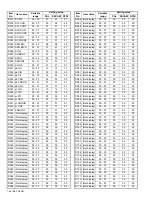


1-20 (No.YA229)
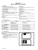
3.4
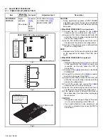
REPLACEMENT OF CHIP COMPONENT
3.4.1 CAUTIONS
(1) Avoid heating for more than 3 seconds.
(2) Do not rub the electrodes and the resist parts of the pattern.
(3) When removing a chip part, melt the solder adequately.
(4) Do not reuse a chip part after removing it.
3.4.2 SOLDERING IRON
(1) Use a high insulation soldering iron with a thin pointed end of it.
(2) A 30w soldering iron is recommended for easily removing parts.
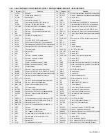
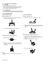
3.4.3 REPLACEMENT STEPS
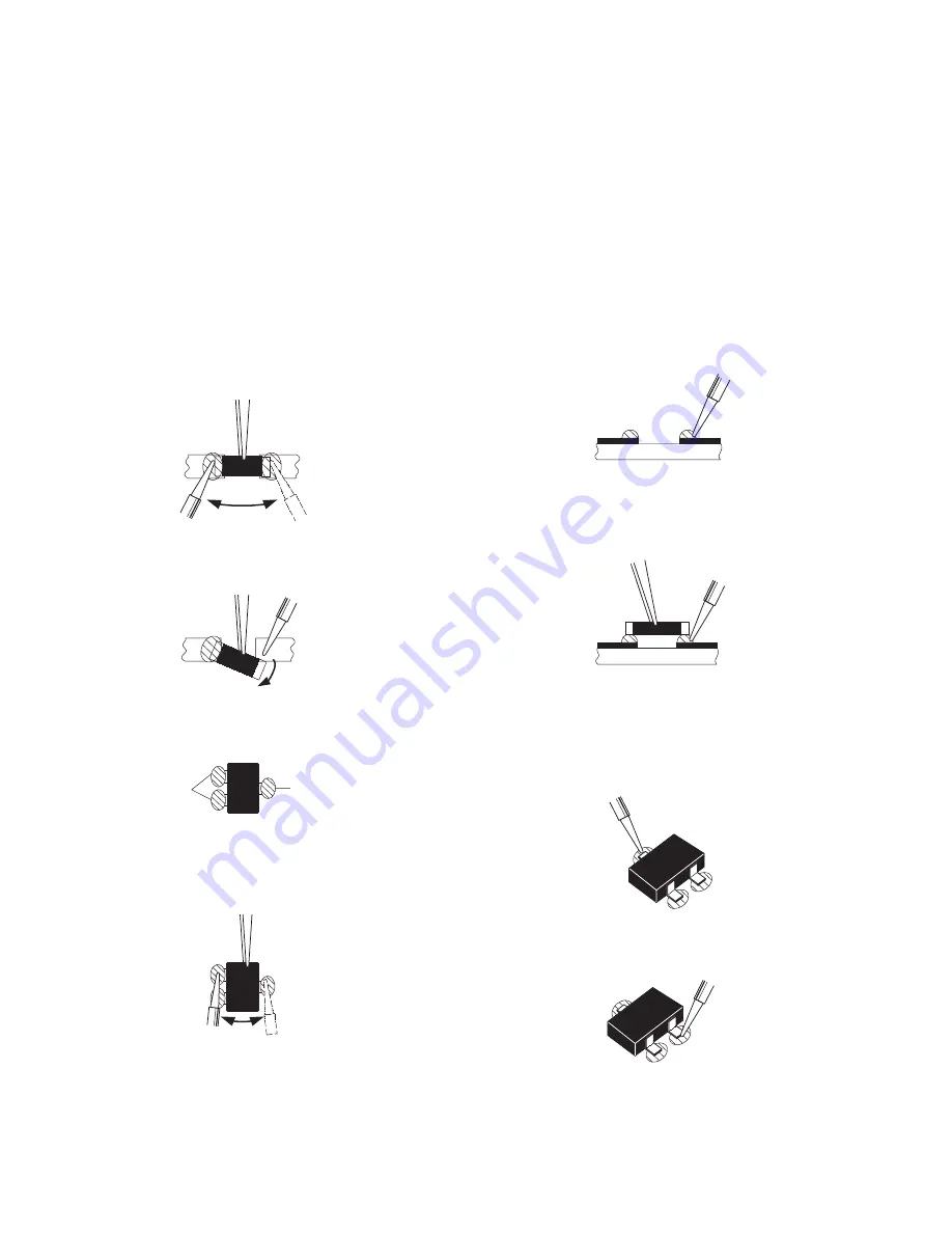
1. How to remove Chip parts
[Resistors, capacitors, etc.]
(1) As shown in the figure, push the part with tweezers and
alternately melt the solder at each end.
(2) Shift with the tweezers and remove the chip part.
[Transistors, diodes, variable resistors, etc.]
(1) Apply extra solder to each lead.
(2) As shown in the figure, push the part with tweezers and
alternately melt the solder at each lead. Shift and remove
the chip part.
NOTE :
After removing the part, remove remaining solder from the
pattern.
2. How to install Chip parts
[Resistors, capacitors, etc.]
(1) Apply solder to the pattern as indicated in the figure.
(2) Grasp the chip part with tweezers and place it on the
solder. Then heat and melt the solder at both ends of the
chip part.
[Transistors, diodes, variable resistors, etc.]
(1) Apply solder to the pattern as indicated in the figure.
(2) Grasp the chip part with tweezers and place it on the
solder.
(3) First solder lead
A
as indicated in the figure.
(4) Then solder leads
B
and
C
.
SOLDER
SOLDER
A
B
C
A
B
C
Summary of Contents for PD-Z50DX4
Page 33: ...PDP COLOUR TELEVISION INSTRUCTIONS PD Z50DX4 ENGLISH LCT1781 001A ...
Page 34: ......
Page 90: ...56 ENGLISH ...
Page 91: ......
Page 92: ... 2004 Victor Company of Japan Limited 1104MKH CR VP ...
Page 98: ...1 6 No YA229B PACKING Page 3 34 FRONT FRONT FRONT FRONT 2 7 8 7 7 7 7 7 7 5 2 7 6 8 3 4 1 ...
Page 105: ...2 4 No YA229 ...


