10
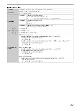
Front
A
[Opt] Indicator
Lights up when an optical fiber cable is connected between
the optical transmitter and optical receiver units, and appears
blinking if cable is not connected.
B
[Sink] Indicator
Lights up when a monitor display is connected. (Monitors
HPD)
C
[Source] Indicator
Lights up when a video signal generator is connected.
(Mo5 V supply)
D
[Dual] Indicator
Lights up when there is a dual-link signal input.
E
MODE
Do not open.
Changing the settings will cause malfunction.
F
STATUS Indicator
This unit performs initialization when the power is turned on.
The initialization takes about 15 seconds.
The STATUS indicator shows the progress of the initialization
with a dotted number.
If the indicator shows "0." to "8." in order and finally "1"
(factory default unit ID), the unit is in working condition.
G
POWER Switch
Use this to turn on/off the main power supply of this unit.
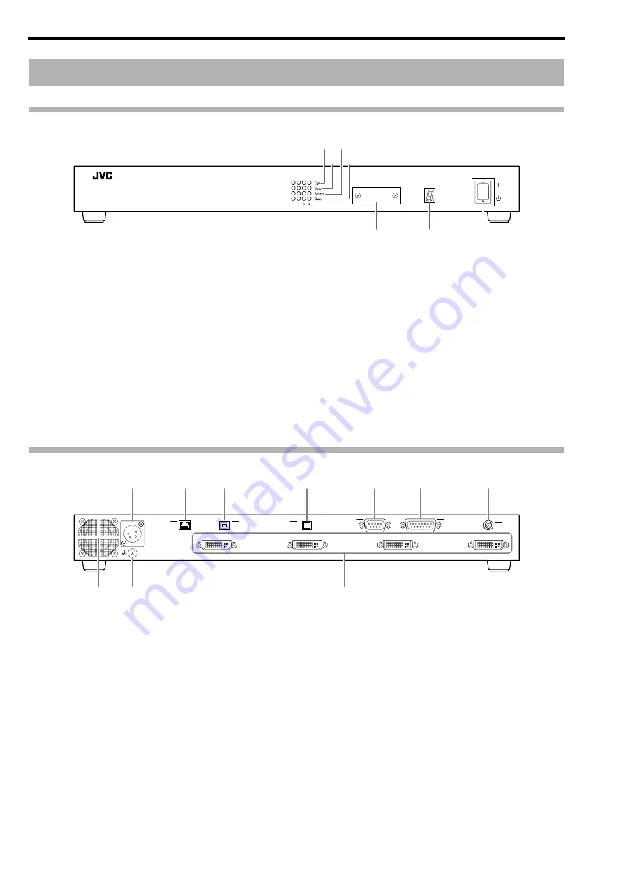
Rear
H
Power Input Terminal
Connect the supplied AC adapter to this terminal.
I
LAN Terminal (RJ-45)
This unit can be controlled by connecting it to a computer
using a LAN cable.
J
USB Terminal (Type B)
This unit can be controlled by connecting it to a computer
using a USB cable.
K
Optical Input Terminal (MPO 12-fiber)
For connecting a 12-fiber MPO connector cable.
L
REMOTE Terminal (D-sub 9 pins)
This unit can be controlled by connecting it to a computer
using a RS-232C cross cable.
M
EXT. CONTROL Terminal (D-sub 15 pins)
This is an extension terminal.
N
SYNC IN Terminal (BNC)
Input terminal for sync signals.
O
Cooling Fan
P
Earth Terminal
Connect the earth wire to this terminal.
Q
DVI OUT to 4 Terminals (DVI-D)
Output terminal for video signals. Connect it to the projector
using a DVI cable.
Names and Functions of Parts
%
&
MODE
STATUS
GRAPHICS INTERFACE
Visualization Series
F
E
A C
B D
G
DC IN 12V
DVI 4 OUT
REMOTE
EXT. CONTROL
DVI 3 OUT
DVI 2 OUT
DVI 1 OUT
SYNC
IN
USB
OPT
LAN
H
I
J
O
P
Q
K
L
M
N
CAUTION
: Do not block the cooling fan with papers, cloth or
soft cushions. Doing so may cause heat to trap
inside the unit and result in fire or malfunction.
Summary of Contents for PK-VS4GD3
Page 28: ......
Page 29: ...GRAPHICS INTERFACE PK VS4GD3 取扱説明書 MODE STATUS GRAPHICS INTERFACE Visualization Series ...
Page 51: ......


