

RC-BX30
No.21171
Dec. 2002
COPYRIGHT 2002 VICTOR COMPANY OF JAPAN, LTD.
SERVICE MANUAL
Contents
Safety precautions
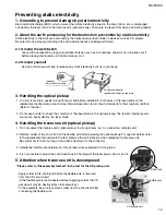
Preventing static electricity
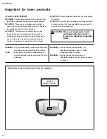
Important for laser products
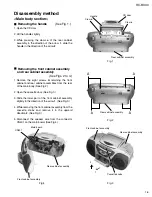
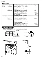
Disassembly method
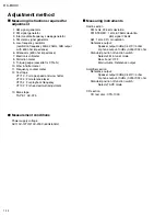
Adjustment method
Trouble shooting
1-2
1-3
1-4
1-5
1-14
1-17
RC-BX30
Area suffix
UJ --------------------- U.S.Military
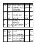
Flow of functional operation
until TOC read
Maintenance of laser pickup
Replacement of laser pickup
Description of major ICs
Wiring connection
1-18
1-19
1-19
1-20
1-22
CD PORTABLE SYSTEM
Summary of Contents for RC-BX30
Page 23: ...RC BX30 1 23 M E M O ...


