


RC-BX30
1-16
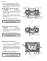
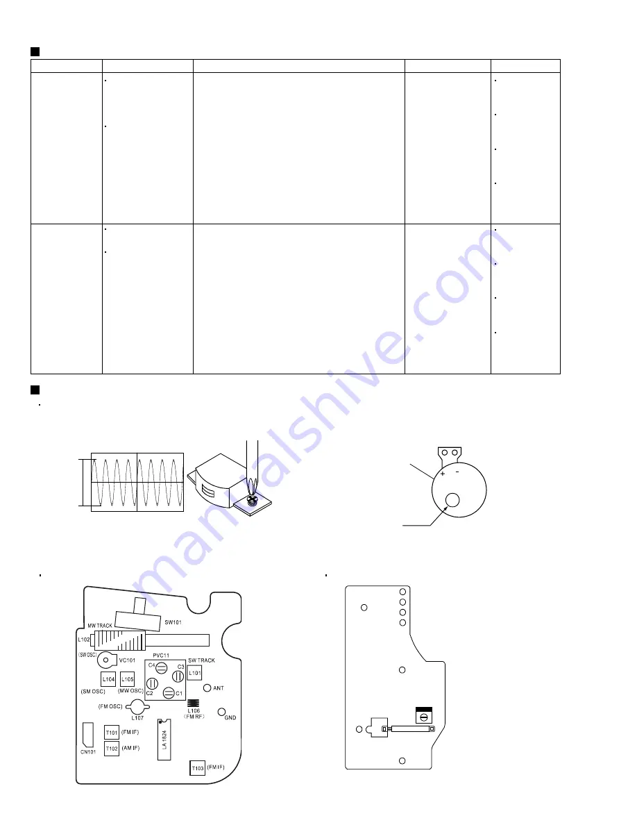
Fig.1 Head output signal
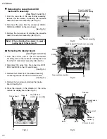
Adjustment
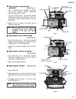
Head
max
Azimuth adjustment screw
CASSETTE MOTOR
Tape Speed Adj.
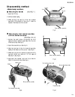
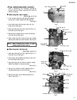
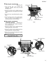
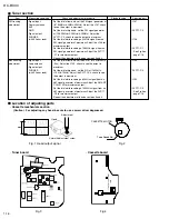
Location of adjusting parts
Cassette mechanism section
Fig.2
(Caution) For adjusting any head, be sure to use a screw driver degaussed.
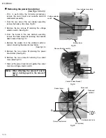
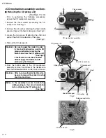
Tuner board
Tuner section
Item
Measuring condition
Check and adjustment procedure
Standard value
Adjusting part
Set the dial at low end, set the FM signal generator at
(87.35MHz+0.2MHz-0.2MHz). Adjust the L107, check
to see the output is maximum.
Set the dial at high end, set the FM signal generator
at (108.25MHz+0.25MHz-0.25MHz). Adjust the
PVC11-C2, check to see the output is maximum.
Set the dial while receiving a 90MHz signal from an
FM signal generator at maximum. Adjust the L106 for
maximum output.
Set the dial while receiving a 106MHz signal from an
FM signal generator at maximum. Adjust the PVC11
-C1 for maximum output.
Repeat the adjustment of the above steps 3 and 4.
Set the dial at low end, set the S/G at (5kHz
-5kz). Adjust the L105, check to see the output is
maximum.
Set the dial at high end, set the S/G at (1620kHz
+15kHz-15kHz). Adjust the PVC11-C4, check to see
the output is maximum.
Set the dial while receiving a 600kHz signal from an
AM signal generator at maximum. Adjust the AM ANT
COIL L102 for maximum output.
Set the dial while receiving a 1400kHz signal from an
AM signal generator at maximum. Adjust the PVC11
-C3 for maximum output.
Repeat the adjustment of the above steps 3 and 4.
Signal input:
Dummy antenna
ANT
GND
Signal output:
PHONES
(with 32 ohm load)
Signal input:
Loop antenna
Signal output:
PHONES
(with 32 ohm load)
FM tracking
adjustment
MW tracking
adjustment
1.
2.
3.
4.
5.
1.
2.
3.
4.
5.
L107
PVC11-C2
L106
PVC11-C1
See Fig.3 on
page 1-16.
L105
PVC11-C4
L102
PVC11-C3
See Fig.3 on
page 1-16.
L201
(Bias Frequency Adj.)
I
I
C
C
1
1
0
0
1
1
Cassette board
Fig.3
Fig.4
Summary of Contents for RC-BX30
Page 23: ...RC BX30 1 23 M E M O ...


