background image

SERVICE MANUAL

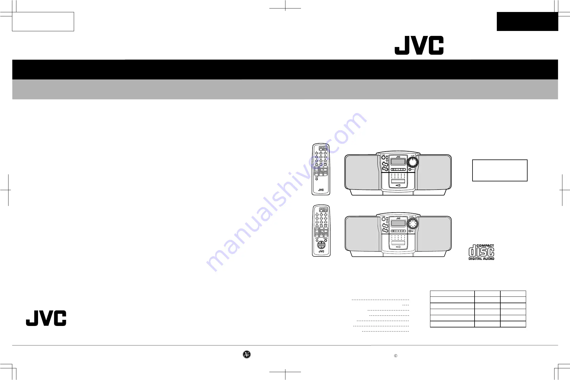
CD PORTABLE  SYSTEM

No.20819

July. 2000

Printed in Japan
200007(S)

RC-BZ5LB/BZ5RD

RC-BZ6BU

(No.20819)

RC-BZ5LB/BZ5RD

RC-BZ6BU

Safety precautions
Importance administering point on the safety 
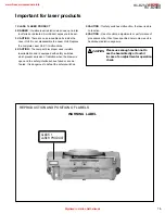
Preventing static electricity
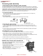
Important for laser products
Disassembly method
Adjustment method
Description of major ICs

RC-BZ5LB/BZ5RD

REMOTE  CONTROL  RM-SRCBZ5

REMOTE  CONTROL  RM-SRCBZ6

RC-BZ6BU

RC-BZ5LB/BZ5RD

RC-BZ6BU

Areas suffix

 J ---------------- U.S.A.

C ------------- Canada

VICTOR COMPANY OF JAPAN, LIMITED

AUDIO & COMMUNICATION BUSINSS DIVISION

PERSONAL & MOBILE NETWORK B.U.   10-1,1Chome,Ohwatari-machi,Maebashi-city,371-8543,Japan

COPYRIGHT     2000 VICTOR COMPANY OF JAPAN, LTD.

1-2
1-3
1-4 
1-5
1-6
1-15
1-18

Contents

Comparison table

Item

 RC-BZ5LB/BZ5RD RC-BZ6BU

Jog dial circuit

Not used

Used

Back light (LCD)

Not used

Used

Bass boost circuit

Not used

Used

Power amplifier

14W

18W

Electrical volume

Not used

Used

www.freeservicemanuals.info

11/28/2017

Digitized in Heiloo Netherlands

Summary of Contents for RC-BZ5LB

Page 1: ...L RM SRCBZ6 RC BZ6BU RC BZ5LB BZ5RD RC BZ6BU Areas suffix J U S A C Canada VICTOR COMPANY OF JAPAN LIMITED AUDIO COMMUNICATION BUSINSS DIVISION PERSONAL MOBILE NETWORK B U 10 1 1Chome Ohwatari machi Maebashi city 371 8543 Japan COPYRIGHT 2000 VICTOR COMPANY OF JAPAN LTD 1 2 1 3 1 4 1 5 1 6 1 15 1 18 Contents Comparison table Item RC BZ5LB BZ5RD RC BZ6BU Jog dial circuit Not used Used Back light LC...

Page 2: ... hazard When service is required the original lead routing and dress should be observed and it should be confirmed that they have been returned to normal after re assembling 5 Leakage current check Electrical shock hazard testing After re assembling the product always perform an isolation check on the exposed metal parts of the product antenna terminals knobs metal cabinet screw heads headphone ja...

Page 3: ...s de feux remplacez le fusible de surete de F902 et F903 comme le meme type que 3A 125V Ce sont des fusibles suretes qui functionnes rapide Importance administering point on the safety For USA and Canada pour Etats Unis d Amerique et Canada F901 Not used J9 POWER TRANSFORMER CN307 CN306 D902 Power supply board D903 D901 F902 F903 D904 R998 S901 www freeservicemanuals info 11 28 2017 Digitized in H...

Page 4: ... to the text 2 Do not use a tester to check the condition of the laser diode in the optical pickup The tester s internal power source can easily destroy the laser diode 4 Handling the traverse unit optical pickup 1 Do not subject the traverse unit optical pickup to strong shocks as it is a sensitive complex unit 2 Remove solder of the land on the flexible cable after replacing the optical pickup F...

Page 5: ...s whichprevent emission of radiation when the drawer is open and the safety interlocks have failed or are de feated It is dangerous to defeat the safety switches 5 CAUTION If safety switches malfunction the laser is able to function 6 CAUTION Use of controls adjustments or performance of procedures other than those specified herein may result in hazardous radiation exposure REPRODUCTION AND POSITI...

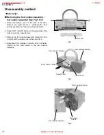
Page 6: ...out the volume knob at the same time Disconnect the speaker harness from connector CN309 on the main board in the rear cabinet assembly 1 2 3 4 Main body assembly rear cabinet assembly See Fig 1 to 3 Disassembly method A A Battery cover Fig 1 Fig 2 Fig 3 STOP EJECT button Front cabinet assembly Rear cabinet assembly Cassette door Volume knob Rear cabinet assembly Front cabinet assembly Main board ...

Page 7: ...and the front cabinet and slide the door arms inward then detach the cassette door from the front cabinet 1 2 Removing the cassette door See Fig 5 and 6 Reattach the door spring to the cassette door shaft with opening the cassette door Fit another end of the door spring to the front cabinet rib Fit the shorter end of the door spring to the cassette door 1 2 3 Reattaching the door spring Front cabi...

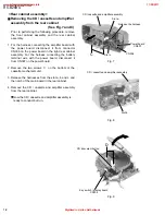
Page 8: ... cassette mechanism unit Release the harnesses from the slot a b and c and the notch of the main board in the rear cabinet Remove the CD cassette and amplifier assembly from the rear cabinet Now the CD cassette and amplifier assembly is ready to conduct burn in 1 2 3 4 Removing the CD cassette and amplifier assembly from the rear cabinet See Fig 7 and 8 Rear cabinet assembly CD cassette and amplif...

Page 9: ...ch board in the direction of the arrow while releasing it from joint d 1 Removing the CD door switch board See Fig 11 Prior to performing the following procedure remove the front cabinet assembly and the rear cabinet assembly Disconnect the card wires from connector CN701 CN702 and CN703 then the harness from CN704 on the key switch display board Remove the four screws E attaching the key switch d...

Page 10: ... the cassette mechanism assembly See Fig 13 to 15 Prior to performing the following procedure remove the CD cassette and amplifier assembly the CD cover and door unit Disconnect the harness from connector P011 on the motor board in the lower part of the CD mechanism assembly Then disconnect the pickup card wire from CN601 on the main board Remove the CD mechanism assembly upward 1 2 Removing the C...

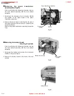
Page 11: ...sses from connector CN301 and CN308 on the main board The harnesses are extending from the cassette mechanism assembly Remove the two screws G on the underside of the main board and release the two joint tabs f from the chassis in the direction of the arrow 1 3 Removing the main board See Fig 17 to 19 Fig 17 Fig 18 Fig 19 CN301 Key switch display bord CN702 CN308 Main board G Main board Chassis g ...

Page 12: ...transformer assembly toward the front 1 2 Removing the power transformer assembly See Fig 20 Prior to performing the following procedure remove the front cabinet assembly and the rear cabinet assembly Disconnect the battery terminal wire from connector CN307 on the power board Remove the battery board on the back of the rear cabinet 1 2 Removing the battery board See Fig 21 and 22 Power transforme...

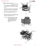
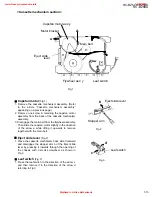
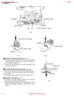
Page 13: ...anism assembly 3 Disengage the main belt from the flywheel assembly Then slide the capstan motor slightly in the direction of the arrow a while lifting it upwards to remove together with the main belt Eject slide lever Fig 2 1 Place the cassette mechanism back side frontward and disengage the stopper arm b of the Eject slide lever by pressing it inwards through the opening of the chassis with a sm...

Page 14: ...e head in the direction of the arrow g 3 Pull out the erase head in the direction of the arrow h Flywheel assembly Fig 7 1 Remove the split washer retaining the flywheel assembly in the direction of the arrow i 2 Pull the flywheel assembly out of the back side of the cassette mechanism assembly in the direction of the arrow j Fig 4 Fig 5 Fig 6 Fig 7 f e B C j Stopper Rec PB head Erase head Capstan...

Page 15: ...tandard position of controls Tone Maximum position Main volume adjust 0 dBs output position Adjustment method Test Instruments required for adjustment Test remarks 1 Negative side of the input and output terminals of the testing set shall be isolated from each other The negative side should not be commonly connected when a 2channel electronic voltmeter is connected 2 A dummy load shall be connecte...

Page 16: ...ghted Frequency 2940 3090 Hz 0 38 or less unweighted Tape speed with semi fixed resistor inside motor Playback output check Function selector TAPE Test tape VT722 VT724 1 kHz Test output from Speaker terminal with 3 Ω load 1 With the test tape VT722 1 kHz signal being played back confirm that the speaker output is 2 1 W or more with 10 distor tion 2 With the test tape VT724 being played back confi...

Page 17: ...t FM AM IF adjustment MPX adjustment FM tracking adjustment Since a solid IF is being used no adjustment is required Since a ceramic resonator is being used no adjustment is required Since a fixed coil is being used no adjustment is required www freeservicemanuals info 11 28 2017 Digitized in Heiloo Netherlands ...
Page 18: ...D TVD FOD FBAL TBAL TOFS TLOCK TES FLOCLK LDON PLAY SENSE WVEL D A CONVERTER OUTPUT PORT SERVO CPU EFM DEMODULATION SYNC INTERPOLATION SUBCODE DEMODULATION MICRO COMPUTER INTERFACE TIMING GENERATOR PITCH CONTROL VCO DSL PLL VCO SUBCODE BUFFER CIRC ERROR CORRECTION DEINTERLEVE 15K SRAM DIGITAL AUDIO INTERFACE CLV SERVO INTER POLATION SOFT MUTING DIGITAL ATTENUATION PEAK DETCT AUTO CUE PWM R PWM L 1...

Page 19: ...TE D BUF D BUF D BUF T S D D BUF D BUF D BUF GND CH4 OUTA CH4 OUTB CH4 INA CH4 INB BIAS IN Vcc CH1 OUTA CH1 OUTB CH1 INA CH1 INB TEST1 TEST2 MUTE Vcc CH3 INB CH3 INA CH3 OUTB CH3 OUTA OP IN OP IN CH2 INB CH2 INA CH2 OUTB CH2 OUTA GND OP OUT BA6897FP IC602 4channel driver 1 Terminal layout Block diagram www freeservicemanuals info 11 28 2017 Digitized in Heiloo Netherlands ...
Page 20: ...ort Low MW mode Not use Not use Data input output Not use Function IF counter signal input IF signal output Not use AM Local OSC signal output FM Local OSC signal input Power supply VDD 4 5 5 5V When power ON Reset circuit move PLL charge pump output H Local OSC frequency Height than Reference frequency L Low Agreement Height impedance Input for active lowpassfilter of PLL Output for active lowpas...

Page 21: ...Vcc AM IF IN FM IF IN GND AGC QUAD R OUT L OUT LPF2 LPF1 MPX IN DET OUT IF REQ ST LED OSC OUT AM OSC FM OSC AM RF IN RF Vcc FM RF OUT RF Stage ground FM RF Input AM Low Frequency Cut Filter External Component Mixer Output Power Supply AM IF Amplifier Input FM IF Amplifier Input Ground AM AGC External Capacitor FM Quadrature Detector Terminal Audio output CH R Audio output CH L LPF Terminal for Pha...

Page 22: ...T TE TEOUT CROSS TEBPF VDET LDOFF VREF ENV 30 24 25 26 23 22 1 4 3 33 32 34 31 36 35 13 14 15 16 20 2 21 6 29 7 28 27 8 9 10 17 11 12 19 ENV CIRCUIT RF DET AGC EQ BDO OFTR VCBA VCBA VCBA VCBA 1 Treminal layout 1 2 3 4 5 6 7 8 9 10 11 12 13 14 15 16 17 18 36 35 34 33 32 31 30 29 28 27 26 25 24 23 22 21 20 19 2 Block diagram www freeservicemanuals info 11 28 2017 Digitized in Heiloo Netherlands ...
Page 23: ...n for tracking error amp Tracking error signal output Tracking error cross output Input pin of tracking error through BPF Vibration detection signal output Reference voltage output Function APC amp input terminal APC amp output terminal APC ON OFF control terminal Envelope output Ground RF detection signal output Of track status signal output BDO output pin A capacitor is connected to this termina...

Page 24: ...OUT2 SEL CDIN2 TAPE RAIN2 MICIN 2 Block diagram 13 12 6 7 19 8 10 11 14 16 15 17 21 23 24 2 3 5 22 46 5 46 5 19 5 NAB AMP1 MIC AMP1 BUF AMP A1 BUF AMP A1 BUF AMP A2 MUTE RADIO LINE TAPE TAPE TAPE ON 18 9 4 20 1 ALC1 DET ALC2 7 26 ON 2 REC AMP1 BUF AMP B1 BUF AMP B2 REC AMP2 MONITOR AMP MUTE MONITOR AMP 1 7 26 ON MUTE L O G I C TAPE LINE RADIO NAB AMP2 REF AMP 2 1V www freeservicemanuals info 11 28...

Page 25: ...RD RC BZ6BU Areas suffix J U S A C Canada VICTOR COMPANY OF JAPAN LIMITED AUDIO COMMUNICATION BUSINSS DIVISION PERSONAL MOBILE NETWORK B U 10 1 1Chome Ohwatari machi Maebashi city 371 8543 Japan COPYRIGHT 2000 VICTOR COMPANY OF JAPAN LTD 1 2 1 4 1 5 1 14 1 17 Contents Comparison table Item RC BZ5LB BZ5RD RC BZ6BU Jog dial circuit Not used Used Back light LCD Not used Used Bass boost circuit Not us...

Page 26: ... parts list Electrical Parts List Packing materials and accessories parts list Contents RC BZ6BU Exploded view of general assembly and parts list Cassette mechanism assembly and parts list CD mechanism assembly and parts list Electrical Parts List Packing materials and accessories parts list 3 14 3 16 3 18 3 19 3 25 3 2 3 4 3 6 3 7 3 13 Areas suffix J U S A C Canada RC BZ5LB BZ5RD RC BZ6BU www fre...

Page 27: ...D mechanism LCD 70 34 54 1 2 3 4 5 6 7 8 9 12 62 43 63 10 11 1 11 2 11 3 11 4 11 5 11 6 13 14 15 55 40 60 61 66 65 67 46 64 16 41 17 18 55 20 23 24 16 16 25 26 27 28 59 30 31 32 33 34 35 36 37 38 16 16 69 68 44 48 50 51 49 52 47 59 Exploded view of general assembly and parts list Block No M M M 1 A A www freeservicemanuals info 11 28 2017 Digitized in Heiloo Netherlands ...
Page 28: ...RD GJ460340190101 C DOOR LENS 1 RC BZ5LB 33 GJ460340220101 FRONT LENS 1 RC BZ5LB GJ460340480101 FRONT LENS 1 RC BZ5RD 34 VYH8007 001 GEAR 2 DOOR 35 GJ460340180101 CASSETTE DOOR 1 36 LV40210 001A DOOR SPRING 1 37 GJ0002 SPGR SPEAKER GRILLE 1 SHILD RC BZ5RD GJ0004 SPGR SPEAKER GRILLE 1 SHILD RC BZ5LB 38 GJ460340010101 FRONT CABINET 1 40 DECK MECHANISM 1 TN 21ZVC 1800 41 GJ702264301412 SCREW TT3X14 2...

Page 29: ...LATE 37 192126502T GEAR PLATE 1 38 19212602T CAM GEAR 1 40 192107304T R F CLUTCH 1 41 19210703T REW F F BELT 1 43 192109303T FLYWHEEL ASSY 1 45 18211070T F FORWARD GEAR 1 46 18211099T BACK TENSION SP 1 47 192105304T S REEL ASS Y 1 48 192105303T T REEL ASS Y 1 49 19210506T SENSOR 1 51 18211289AT MOTOR BRACKET 1 53 19211202T COLLAR SCREW 2 SP MOTOR 3X6 54 19211201T MOTOR PULLEY 1 55 19210904T MAIN B...

Page 30: ...RC BZ5LB BZ5RD 3 5 TN 21ZVC 1800 Cassette mechanism assembly and parts list Block No M M M 2 Pulley hight dimension 7 6 0 1 www freeservicemanuals info 11 28 2017 Digitized in Heiloo Netherlands ...

Page 31: ... A Parts list CD mechanism assembly Q ty Description Block No M3MM 1 GJ560280020101 MECHA BASE 1 2 OPTIMA 7B CD PICK UP 1 3 E407782 001 PICK STAFT 1 4 E307746 001 CD RACK GEAR 1 GEAR SHAFT 5 GJ560280010101 MECHA GEAR 1 6 GJ50312003102 SCREW MZX3 B H 4 7 E406750 001 PINION GEAR 1 8 GJA2062001001C CD TURN TABLE 1 9 GJ90028678400 FEED MOTOR 1 10 GJ90028678300 SPINDLE MOTOR 1 11 GJ100069000100 MECH CI...

Page 32: ...1022432 M CAPACITOR POLY FILM 50V K C 202 GJ283105622432 M CAPACITOR POLY FILM 50V K C 203 GJ270122260332 E CAPACITOR 16V M 22UF C 204 GJ282033932415 M CAPACITOR FILM 50V J 0 03 C 205 GJ270193350332 E CAPACITOR 50V M 3 3UF C 207 GJ270194750332 E CAPACITOR 50V VX M 4 7UF C 208 GJ270191050332 E CAPACITOR 50V M 1UF C 214 GJ270194750332 E CAPACITOR 50V VX M 4 7UF C 219 GJ270194740332 E CAPACITOR 50V M...

Page 33: ...D 8 KV1555N T VARI CAPACITOR GJ310050040103 D 12 IN4001 DIODE RECT BULK D 303 1SS133Y DIODE GJ871999133 D 305 1SS133Y DIODE GJ871999133 D 307 1SS133Y DIODE GJ871999133 D 661 1SS133Y DIODE GJ871999133 D 901 1N5401 M SI DIODE A D 902 1N5401 M SI DIODE A D 903 1N5401 M SI DIODE A D 904 1N5401 M SI DIODE A D 905 1SS133Y DIODE GJ871999133 D 907 1SS133Y DIODE GJ871999133 D 908 1SS133Y DIODE GJ871999133 ...

Page 34: ...F 1 6W J 10K R 133 GJ250081822103 CARBON RESISTOR CF 1 6W J 1 8K R 134 GJ250083922103 CARBON RESISTOR CF 1 6W J 3 9K R 135 GJ250084732103 CARBON RESISTOR CF 1 6W J 47K R 137 GJ250086822103 CARBON RESISTOR CF 1 6W J 6 8K R 204 GJ250083322103 CARBON RESISTOR CF 1 6W J 3 3K R 206 GJ250083932103 CF RESISTOR CF 1 6W J 39K R 207 GJ250088202103 RES CF CF 1 6W J 82 R 208 GJ250081532103 CARBON RESISTOR CF ...

Page 35: ...ISTOR CF 1 6W J 3 3K R 909 GJ250081022103 CARBON RESISTOR CF 1 6W J 1K R 910 GJ250081042103 CARBON RESISTOR CF 1 6W J 100K R 911 GJ250084722103 CARBON RESISTOR CF 1 6W J 4 7K R 912 GJ250081022103 CARBON RESISTOR CF 1 6W J 1K R 913 GJ250085622103 CARBON RESISTOR CF 1 6W J 5 6K R 914 QRZ0077 4R7X FUSE RESISTOR A 1 4W J 4 7 TAPE R 915 GJ250081012103 CARBON RESISTOR CF 1 6W J 100 R 916 GJ250088212103 ...

Page 36: ...00K 1 10W 5 R 721 GJ121605791 C RESISTOR 2 2K 1 10W 5 R 723 GJ121607391 C RESISTOR 10K 1 10W 5 R 724 GJ121605791 C RESISTOR 2 2K 1 10W 5 R 725 GJ121605791 C RESISTOR 2 2K 1 10W 5 R 726 GJ121605791 C RESISTOR 2 2K 1 10W 5 R 727 GJ121605791 C RESISTOR 2 2K 1 10W 5 R 728 GJ121607391 C RESISTOR 10K 1 10W 5 R 729 GJ121608991 C RESISTOR 47K 1 10W 5 R 730 GJ121607391 C RESISTOR 10K 1 10W 5 R 732 GJ121609...

Page 37: ...0171110 S 865 QSW0707 001Z TACT SWITCH GJ390110171110 S 866 GJ390030152203 SWITCH PUSH SW PSG 22F0US Q3 5 VR302 QVQ0121 A54 MAIN VOL GJ299000490002 WR701 GJ354004030205 WIRE CN704 TO CD DO WR702 GJ354004040105 WIRE CN702 TO MAIN X 701 QAX0410 001Z CERA LOCK MIZCRHF 4 19MHZ Electrical parts list System CPU board Block No 02 www freeservicemanuals info 11 28 2017 Digitized in Heiloo Netherlands ...
Page 38: ...er Parts name Area A Accessories parts list Q ty Description Block No M5MM A 1 GJ350161831129 POWER CORD A 1 7A 120V 1 80M A 2 GJ773012200101 INTRUCTIONS J C 1 ENG SPA FRE A 3 BT 20044G ACC SAFETY GUID J C 1 GJ775000140101 A 4 GJ775000200202 SERVICE LIST J C 1 A 5 GJ775000340101 SVC CENTER LIST J C 1 A 6 GJ773030190302 WARRANTY CARD J 1 A 7 GJ773030290101 WARRANTY CARD C 1 A 8 GJA1002014001C REMOC...

Page 39: ...nism LCD 70 34 54 1 2 3 4 5 6 7 8 9 12 62 43 63 10 11 1 11 2 11 3 11 4 11 5 11 6 13 14 15 58 40 60 61 66 65 67 46 64 16 41 17 18 58 20 55 56 57 23 24 16 16 25 26 27 28 59 31 32 33 36 38 16 16 69 68 44 48 50 51 49 52 47 59 Exploded view of general assemble and parts list Block No M M M 1 A A 30 34 35 37 www freeservicemanuals info 11 28 2017 Digitized in Heiloo Netherlands ...

Page 40: ...05 SPGR SPEAKER GRILLE 1 SHILD 31 GJ460340240101 VOLUME KNOB 1 32 GJ460340190101 C DOOR LENS 1 33 GJ460340220101 FRONT LENS 1 34 VYH8007 001 GEAR DANPER 2 DOOR 35 GJ460340180101 CASSETTE DOOR 1 36 LV40210 001A DOOR SPRING 1 37 GJ0006 SPGR SPEAKER GRILLE 1 SHILD 38 GJ460340010101 FRONT CABINET 1 40 DECK MECHANISM 1 TN 21ZVC 1800 41 GJ702264301412 SCREW TT3X14 2 43 GJ711001340101 SPRING 1 ANT CONTAC...

Page 41: ... 38 19212602T CAM GEAR 1 40 192107304T R F CLUTCH 1 41 19210703T REW F F BELT 1 43 192109303T FLYWHEEL ASSY 1 45 18211070T F FORWARD GEAR 1 46 18211099T BACK TENSION SP 1 47 192105304T S REEL ASS Y 1 48 192105303T T REEL ASS Y 1 49 19210506T SENSOR 1 51 18211289AT MOTOR BRACKET 1 53 19211202T COLLAR SCREW 2 SP MOTOR 3X6 54 19211201T MOTOR PULLEY 1 55 19210904T MAIN BELT 1 56 19211203T MB SCREW 1 S...

Page 42: ...RC BZ6BU 3 17 TN 21ZVC 1800 Cassette mechanism assembly and parts list Block No M M M 2 Pulley hight dimension 7 6 0 1 www freeservicemanuals info 11 28 2017 Digitized in Heiloo Netherlands ...

Page 43: ...A Parts list CD mechanism assembly Q ty Description Block No M3MM 1 GJ560280020101 MECHA BASE 1 2 OPTIMA 7B C D PICK 1 3 E407782 001 PICK STAFT 1 4 E307746 001 CD RACK GEAR 1 GEAR SHAFT 5 GJ560280010101 MECHA GEAR 1 6 GJ50312003102 SCREW MZX3 B H 4 7 E406750 001 PINION GEAR 1 8 GJA2062001001C CD TURN TABLE 1 9 GJ90028678400 FEED MOTOR 1 10 GJ90028678300 SPINDLE MOTOR 1 11 EMW10190 001 S MECH CIR B...

Page 44: ...GJ270122260332 E CAPACITOR 16V M 22UF C 130 GJ260772212412 C CAPACITOR C 50V SL J 220P C 134 GJ283105622432 M CAPACITOR 50V K 0 0056UF C 155 GJ264141812101 C CAPACITOR 50V B K 180PF C 201 GJ283101022432 M CAPACITOR 50V K 0 001UF C 202 GJ283105622432 M CAPACITOR 50V K 0 0056UF C 203 GJ270122260332 E CAPACITOR 16V M 22UF C 204 GJ282033932415 M CAPACITOR 50V J 0 039UF C 207 GJ270194750332 E CAPACITOR...

Page 45: ...1 C CAPACITOR 16V Y M 0 01UF C 914 GJ270112270332 E CAPACITOR 10V M 220UF C 915 GJ270111070332 E CAPACITOR 10V M VX 100UF C 916 GJ270114760332 E CAPACITOR 10V M 47UF CF 1 QAX0403 001 C FILTER FM 10 7M CF 3 QAX0538 001Z CRYSTAL FM CDA10 7 CN301 GJ156450711 CONNECTOR 4PINS ST CN303 QGF1212C1 13 FFC CONNECTOR 13PIN CN304 QGF1212C1 17 FFC CONNECTOR 17PINS CN306 TID X03P MI CONNECTOR 3 PINS RA WHIT CN3...

Page 46: ...J250081022103 CARBON RESISTOR 1 6W J 1K R 60 GJ250081022103 CARBON RESISTOR 1 6W J 1K R 61 GJ250081022103 CARBON RESISTOR 1 6W J 1K R 63 GJ250084732103 CARBON RESISTOR 1 6W J 47K R 64 GJ250081022103 CARBON RESISTOR 1 6W J 1K R 101 GJ250083022103 CARBON RESISTOR 1 6W J 3 0K R 102 GJ250081022103 CARBON RESISTOR 1 6W J 1K R 103 GJ250081822103 CARBON RESISTOR 1 6W J 1 8K R 104 GJ250083322103 CARBON RE...

Page 47: ...03 CARBON RESISTOR 1 6W J 4 7K R 651 GJ250081022103 CARBON RESISTOR 1 6W J 1K R 652 GJ250081022103 CARBON RESISTOR 1 6W J 1K R 653 GJ250081022103 CARBON RESISTOR 1 6W J 1K R 654 GJ250081022103 CARBON RESISTOR 1 6W J 1K R 659 GJ250082712103 CARBON RESISTOR 1 6W J 270 R 661 GJ250086832103 CF RESISTOR 1 6W J 68K R 663 GJ250081242103 CARBON RESISTOR 1 6W J 120K R 664 GJ250084712103 CARBON RESISTOR 1 6...

Page 48: ...121607391 C RESISTOR 10K 1 10W 5 R 707 GJ121607391 C RESISTOR 10K 1 10W 5 R 708 GJ121607391 C RESISTOR 10K 1 10W 5 R 709 GJ121608191 C RESISTOR 22K 1 10W 5 R 710 GJ121609791 C RESISTOR 100K 1 10W 5 R 711 GJ121608191 C RESISTOR 22K 1 10W 5 R 712 GJ121607391 C RESISTOR 10K 1 10W 5 R 713 GJ121607391 C RESISTOR 10K 1 10W 5 R 714 GJ121608791 C RESISTOR 39K 1 10W 5 R 715 GJ121608591 C RESISTOR 33K 1 10W...

Page 49: ...W 5 R 864 GJ121606791 C RESISTOR 5 6K 1 10W 5 R 865 GJ121605791 C RESISTOR 2 2K 1 10W 5 S 851 QSW0707 001Z TACT SWITCH GJ390110171110 S 852 QSW0707 001Z TACT SWITCH GJ390110171110 S 853 QSW0707 001Z TACT SWITCH GJ390110171110 S 854 QSW0707 001Z TACT SWITCH GJ390110171110 S 855 QSW0707 001Z TACT SWITCH GJ390110171110 S 856 QSW0707 001Z TACT SWITCH GJ390110171110 S 857 QSW0707 001Z TACT SWITCH GJ390...

Page 50: ...name Area A Accessories parts list Q ty Description Block No M5MM A 1 GJ350161831129 POWER CORD A 1 7A 120V 1 80M A 2 GJ773012130101 INSTRUCTIOS J C 1 ENG SPA FRE A 3 BT 20044G ACC SAFETY GUID J C 1 GJ775000140101 A 4 GJ775000200202 SERVICE LIST J C 1 A 5 GJ775000340101 SVC CENTER LIST J C 1 A 6 GJ773030190302 WARRANTY CARD J 1 A 8 GJA1002015001C REMOCON UNIT 1 A 9 GJ460340320102 COVER BATTERY 1 R...

Page 51: ...e Feed Forcus Tracking F T Coil IC1 IC2 PLL IC302 Q101 Q201 Q302 L4 T2 CF1 J301 L3 AM BPF L1 B BP1 Q101 Tuner L R REC PB CN301 R P HEAD CN601 SPINDLE FEED MOTOR M M RCH LCH CN702 FW302 Main Volume SMUTE LCH RCH LCH RCH CN309 R CH L CH SPEAKER CN303 IC701 SYSTEM CONT SMUTE CN703 FM RF IF DET MPX AM RF IF DET Power Amp www freeservicemanuals info 11 28 2017 Digitized in Heiloo Netherlands ...
Page 52: ...d Forcus Tracking F T Coil IC1 IC2 PLL IC302 Q101 Q201 Q302 L4 T2 CF1 J301 L3 AM BPF L1 B BP1 Q101 REC PB CN301 R P HEAD CN601 SPINDLE FEED MOTOR M M RCH LCH SMUTE LCH RCH LCH RCH CN309 R CH L CH SPEAKER CN303 IC701 SYSTEM CONT SMUTE CN703 IC304 Bass Boost Amp Tuner L R L OSC FM RF IF DET MPX AM RF IF DET Power Amp www freeservicemanuals info 11 28 2017 Digitized in Heiloo Netherlands ...
Page 53: ...OUND S865 QSW0707 001Z R858 5 6K R859 18K R860 330 R861 680 R864 5 6K Q851 2SA1037AK RS X D851 LTD3116 41 D852 LTD321 41 R851 1 5K R852 1 8K R853 2 7K R854 3 9K R855 6 8K R856 12K R857 39K 1 2 S866 VMW14774 D 1 2 FW701 P8 22F23 A3 3NS TO MAIN AMP SECTION TO A 1 on page 2 7 8 3V 6 8V 0 7V 2 1V 5 7V 0V 5 0V 4 6V 5 1V 4 8V 5 0V 6 1V 0 1V 5 1V 5 0V 0V CD DOOR SW CD B SAFETY FCD MLD XRST TAPE REC AC DC...

Page 54: ...CAPACITOR ALL CAPACITANCE VALUES ARE IN uF p pF ALL INDUCTANCE VALUES ARE IN uH m mH ALL E CAPACITORS ARE SHOWN IN THE FORM OF CAPACITANCE uF RATED VOLTAGE V LIST U UP US UT UX UY UZ E B EN J C R789 R785 10K 10K 22K 8 2K 2 2K PARTS NAME CONSTRUCTION DTC143TKA DTC144EKA 4 7K 47K 47K RESET 1 2 3 4 5 6 7 8 9 10 11 12 13 CN703 QGF1212F1 13 0V 0V 1 2 1 2 FW702 Q852 2SC2412K R X Q709 2SC2412K R X R790 4...

Page 55: ... 0 0022 C623 0 1 C617 0 022 C620 180P C619 270P R607 27K R610 150K R612 1K R609 100K R605 270K R606 150K R601 11K R603 1 2M C614 0 1 C609 100P C610 0 027 C611 0 0047 C612 0 01 C608 1 50 C629 100 10 C628 0 047 R623 33 R621 33 R622 33 K601 QQR0779 001Z K602 QQR0779 001Z 1 14 2 15 3 4 5 6 7 8 9 10 11 12 13 CN601 QGF1025C1 15 C622 47 10 R613 120 R616 91 R615 12 R614 10 Q601 2SA952 LK T 1 2 3 4 5 6 CN6...

Page 56: ...QAT7002 200Z C22 430P C23 12P C21 0 047 R13 100K K1 QR0779 001Z R18 1K R37 56 TO ROD ANT TP1 FM GND TP2 FM RF CC CH CH FM OSC BAR ANT CC PP CH MW OSC FM RF IF EDT MPX AM RF IF DET CC FM IF CC CC ANT GND GND TUR TUL TUSW6V MPX SDATA SCK TUST TO MAIN SECTION PLL PIN NO IC1 IC2 PIN NO IC1 IC2 FM NO SIGNAL FM 60dB STEREO AM NO SIGNAL FM NO SIGNAL FM NO SIGNAL FM 60dB STEREO AM NO SIGNAL FM NO SIGNAL 1...

Page 57: ... 2 3 FW301 1 2 3 TID X03P M1 Q318 DTA143ES T Q310 DTA143ES T Q308 DTC143ES T Q309 R328 10K R373 100 C354 220 10 1 2 3 4 5 6 1 2 3 4 5 6 CN308 QG42501C4 06 D918 REC SW LEAF SW LEAF SW M 1 2 3 CN306 TTL25L 003 1 2 3 FW905 1 2 3 1 2 3 CN307 5268 03A C902 0 022 C904 0 022 C901 0 022 C903 0 022 D903 IN5401 TNC D902 IN5401 TN D901 IN5401 TN D904 IN5401 TN R999 330 POWER CORD F902 R320 5 6K ANTGND GND TU...

Page 58: ...CN301 DGA2501C4 03 R237 6 8K R137 6 8K D917 D307 R356 10K C709 2200 5 3 Q316 2SA1015 YG T Q306 8550D Q901 2SB772 QP Q908 2SB772 QP Q906 B550D OR 8550C Q903 8550D OR 8550C Q902 2SC2458 YG T Q907 Q904 Q909 Q911 Q305 DTC114ESA T D914 D915 D906 D905 D910 D911 D907 D995 D908 D909 ZD904 MTZJ5 6B ZD903 MTZJ6 2B R321 5 6K R332 10K R901 4 7K R903 100 R902 56K R904 820 R910 100K R914 4 7 R912 1K R911 4 7K R...

Page 59: ...6 5 4 3 2 1 B C D E F G H I J A 7 RC BZ5LB BZ5RD RC BZ6BU 2 9 Printed circuit boards Main board Block No 01 www freeservicemanuals info 11 28 2017 Digitized in Heiloo Netherlands ...
Page 60: ... 2 1 B C D E F G H I J A 7 RC BZ5LB BZ5RD RC BZ6BU 2 10 System CPU board RC BZ5LB BZ5RD Block No 02 System CPU board RC BZ6BU Block No 02 www freeservicemanuals info 11 28 2017 Digitized in Heiloo Netherlands ...
Reviews: