background image

SERVICE MANUAL

CD PORTABLE SYSTEM

RC-EZ31A

No: 28225
JAN. 2006

COPYRIGHT 

©

 2006 JVC ASIA PTE LTD

 Area Suffix

 US ----- Asia
 UX ----- Middle East
  A   ----- Australia

  SERVICE POLICY

 No service part is available for this model.
 Based on One to One exchange policy.

Contents

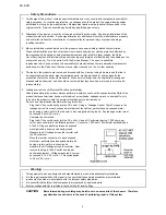
Safety precaution ............................................................................ 2
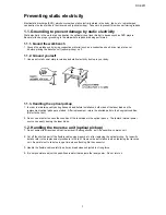
Preventing static electricity ............................................................. 3
Disassembly procedure ................................................................... 4
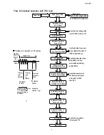
Flow of function operation until TOC read ...................................... 5
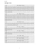
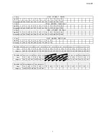
Voltage charts ................................................................................. 6
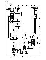
Block diagram ................................................................................. 8
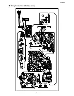
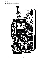
Wiring connection ........................................................................... 9
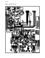
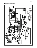
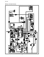
Schematic diagrams ...................................................................... 11
Illustration of packing and parts list ............................................... 18

Summary of Contents for RC-EZ31A

Page 1: ... SERVICE POLICY No service part is available for this model Based on One to One exchange policy Contents Safety precaution 2 Preventing static electricity 3 Disassembly procedure 4 Flow of function operation until TOC read 5 Voltage charts 6 Block diagram 8 Wiring connection 9 Schematic diagrams 11 Illustration of packing and parts list 18 ...

Page 2: ...bling 5 Leakage current check Electrical Shock hazard testing After re assembling the product always perform an isolation check on the exposed metap Parts of the product antenna terminals knobs metal cabinet screw heads headphone jack control shafts etc to be sure the product is safe to operate without danger of electrical shock Do not use a line isloation transformer during this check Plug the AC...

Page 3: ...cikup 1 In order to maintain quality during transport and before installation both sides of the laser diode on the replacement optical pickup are storted After replacement return the shorted parts to their original condition Refer to the text 2 Do not use a tester to check the condition of the laserdiode in the optical pickup The tester s internal power source can easily destory the laser diode 1 ...

Page 4: ...ove the back cabinet Screw A 1 Open battery cover and remove 3 screws on the bottom cabinet Screw A 2 Remove 5 screws on back Screw B Screw B Remove the top panel 1 Remove 3 screws to take Screw C out the top panel with the board Screw C Then the unit is disassembled ...

Page 5: ...ower Key Slider turns REST SW ON Automatic tuning of TE offset Laser ON Detection of disc Automatic tuning of Focus offset Automatic measurement of focus A curve amplitude Disc is rotated Focus servo ON Tracking servo ON Automatic measurement of Tracking error amplitude Automatic tuning of Tracking error balance Automatic tuning of Focus error balance Automatic tuning of Focus error gain Automatic...

Page 6: ...3 2 39 2 41 pin NO 61 62 63 64 Votage v 2 23 3 79 0 22 4 94 IC No Item 1 2 3 4 5 6 7 8 9 10 11 12 13 14 15 16 17 18 19 20 DC12V 3 55 3 13 2 15 2 15 6 60 5 18 2 18 0 10 2 19 2 19 3 65 3 15 0 10 6 85 0 90 0 90 3 50 3 30 2 20 2 20 Item 21 22 23 24 25 26 27 28 DC12V 7 34 7 34 2 20 2 20 2 20 3 40 3 40 0 10 IC No pin NO 1 2 3 4 5 6 7 8 9 10 11 12 13 14 15 16 17 18 19 20 Votage v 0 85 0 00 0 31 5 44 0 51...

Page 7: ... C E B C E B C E B C 8 50 9 11 11 96 0 00 0 70 0 00 0 00 0 00 0 70 0 00 0 00 0 00 0 00 0 00 0 00 0 00 0 00 0 00 E B C E B C E B C E B C 0 00 0 00 0 00 11 93 11 20 0 02 4 90 0 00 0 00 0 00 0 70 0 00 E B C E B C E B C E B C E B C E B C 13 40 12 70 13 36 4 57 5 24 8 47 IC301 UTC8227 CD PLAY IC301 UTC8227 CASS PLAY IC301 UTC8227 TUNER Votage v Q401 D2061 CD PLAY IC201 BA3308 CASS PLAY Q329 9014 CDPLAY...

Page 8: ...XL SV320SL SV305GD XL SV308BU 8 RC EZ31 Block Diagram ...

Page 9: ...RC EZ31 9 Wiring Connections US UX version ...

Page 10: ...XL SV320SL SV305GD XL SV308BU 10 RC EZ31 Wiring Connections A version ...

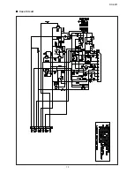
Page 11: ...RC EZ31 11 Schematic Diagrams Main Circuit US UX Version ...

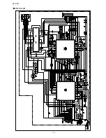
Page 12: ...XL SV320SL SV305GD XL SV308BU 12 RC EZ31 Main Circuit A Version ...

Page 13: ...RC EZ31 13 Tuner Circuit US UX Version ...

Page 14: ...XL SV320SL SV305GD XL SV308BU 14 RC EZ31 Tuner Circuit A Version ...

Page 15: ...RC EZ31 15 Cass Circuit ...

Page 16: ...XL SV320SL SV305GD XL SV308BU 16 RC EZ31 CD Circuit ...

Page 17: ...RC EZ31 17 Control Circuit ...

Page 18: ...Remote Control Unit P 11 Poly Bag P 12 Gift Box G B P 13 G B Bar Code Label 612 080350 000 612 080348 000 P 14 Battery AAA x 2pcs P 15 POP Label Remarks Alt items will be used alternatively depends on the lead time 163 200415 900 676 070100 040 629 080284 000 JVC LVT1524 001A LVT1524 002A RM SRCEZ31A 891 EZ3111 010 874 310000 000 874 310000 000 676 040130 044 678 255175 040 P12 P1 P8 P9 P2 P6 P7 P...

Page 19: ... JVC LVT1524 003A P 8 Poly Bag 676 070100 040 P 9 Remote Control Unit P 10 Poly Bag RM SRCEZ31A P 11 G B Bar Code Label 612 080352 000 P 12 Gift Box G B 891 EZ3111 020 P 13 Battery AAA x 2pcs 163 200415 900 Illustraction of packing and parts list A Version P11 P1 P7 P8 P2 P5 P6 P13 P10 P9 P4 P3 P12 PROGRAM REPEAT REMOTE SENSOR CD PORTABLE SYSTEM RC EZ31 RE MO TE CO NT RO L UN IT RM SR CE Z31 A SK ...

Page 20: ...JVC Asia Pte Ltd 101 Thomson Road 28 04 United Squares Singapore 307591 No 28225 Printed in Singapore 200601 L ...

Reviews: