

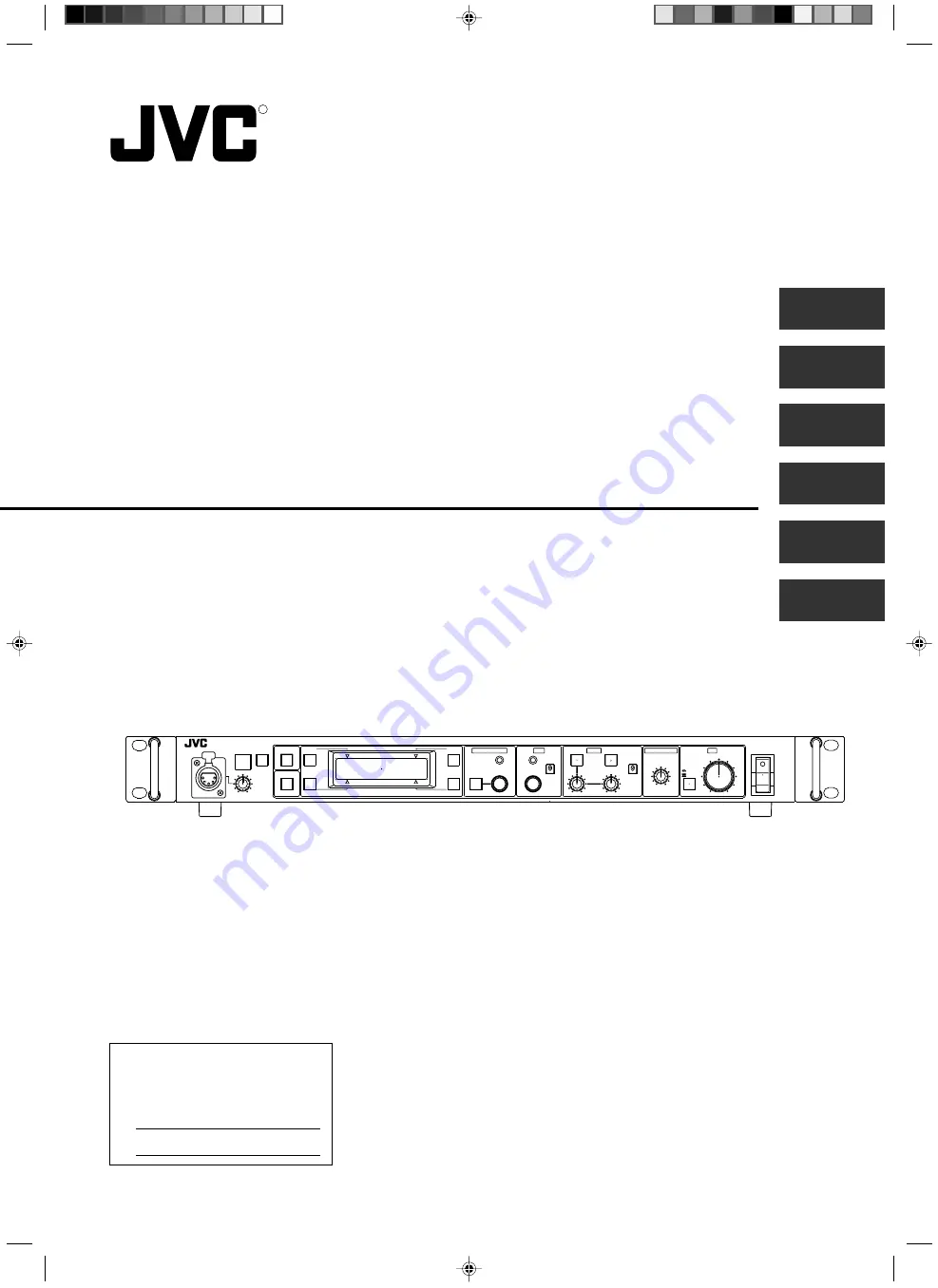
INSTRUCTIONS
REMOTE CONTROL UNIT
RM-P210
RM-P210 REMOTE CONTROL UNIT
SC961002-003-H
R
d
For Customer Use:
Enter below the Model No. and Serial
No. which are located on the bodie.
Retain this information for future reference.
Model No. RM-P210
Serial No.
INTRODUCTION
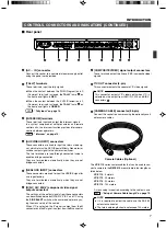
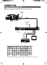
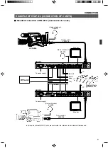
CONNECTION
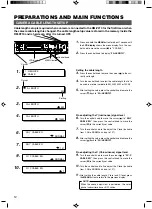
PREPARATIONS AND
MAIN FUNCTIONS
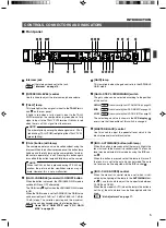
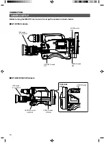
GENERAL
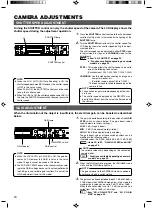
CAMERA
ADJUSTMENTS
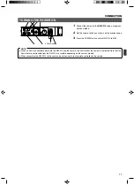
MENU OPERATION
CALL
TALLY
INTERCOM
LEVEL
FULL AUTO
F1
SHUTTER
GAIN
F2
F3
MENU/SHUTTER
GAIN
PAINT
AUTO
B
R
W.BAL
AUTO
MANU
WHITE
MASTER BLACK
POWER
I
O
IRIS
STEP
SHUTTER
MENU
PUSH-ON
DOWN
UP
VARIABLE
PUSH-ON
HIGH
LOW
B
A
PRESET
CLOSE
OPEN
MID
DOWN
UP
F4
BARS
REMOTE CONTROL UNIT RM-P210


